This site (still growing) covers vacuum tube (valve) theory from a guitar amp perspective. I have been watching this site grow over the past year and it now contains plenty of information useful to amplifier builders both MI and HiFi. A newly posted paper called "the triode gain stage" goes into detail on how to design one, and how to get several different flavors of distortion out of it (or how not to). Several circuit variations are presented.
http://www.freewebs.com/valvewizard/index.html
http://www.freewebs.com/valvewizard/index.html
Hi,
I haven't checked everything on this site but it seems that it contains some faulty information.
Look at the chapter of Cathodyne splitter where they convey the old false statement that the output impedance is different from cathode and anode and they even advice the use of a series resistance on the cathode side to "equalise" the driving impedance to the next stage.
In reality there is nothing to equalise as the ou2put impedances are equal.
It would be nice if a site that claim to be the "Valve Wizard "did teach what is correct and not the opposite.
Regards Hans
The output impedances are not equal , but if the loads are equal , the balance of the stage is perfect . Look here : www.aikenamps.com/cathodyne.pdf And they say to add a resistor in a guitar amplifier for imbalance ( more distortions ) .
Sorry but you have interpreted the text wrong, that text confirms that the the output impedances ARE equal, Quote "In the case of the phase splitter circuit Zk=Zl=Z" (page 2 in the middle).
The ouput impedance can be calculated as Rout = RL*ra/(RL*(µ+2)+ra) Where RL is the anode or cathode resistor, ra is the anode resistance of the tube.
This subject has been discussed many times on this forum and the correct calculation of the ouput impedances is described in many books e.g Morgan Jones Valve amplifiers 3rd edition.
That a faulty description is circulated in many web forums and even in some books doesn't make it more less faulty.
The reason for the mistake in calculation is that the output impedance of the anode and cathode is calculated separately which of course is wrong as both sides are loaded, calculating the output impedances with both sides loaded give the result above. It is very easy to confirm this by either a spice simulation or measurements in a real amplifier, I have both simulated and measured the output impedances and can confirm that it is correct, it is interesting to notre that the output impedance is so low, in my case with a 12BH7 and 15k anode resistor you get ~300ohm.
Adding a resistor from the cathode will introduce imbalance and increase distortion.
Regards Hans
I didn't interpreted the text wrong , Zk , Zl are the load impedances . The general formulas are those from my text , Zop and Zok , and only if you put the condition that loads are equal , the output impedances ( anod and cathode ) are equal.
It's wrong to say that output impedances are equal ( there are not ) without specify the load condition.
It's wrong to say that output impedances are equal ( there are not ) without specify the load condition.
This is a phase splitter is it not? In that case the loads are equal, and then the output impedances ARE equal. The only valid definition of what output impedance you have in a circuit is how it behaves e.g how the frequency response is affected and how it reacts on differences in load conditions e.g if you change the following stage grid resistors, and the only to measure it is during the same conditions, any other measurents are not valid as they don't reflect the real operating conditions. Therefore we can conclude that the output impedances of a cathodyne phase splitter are equal and it is therefore completely wrong to add any series resistor from the cathode.
Regards Hans
Regards Hans
I came across this website through a link that was posted some time ago here at diyaudio. It will be the website I will refer to when somebody asks for "an introduction to valve amplifiers".
About the cathodyne. I do not have Valve Amplifiers handy, but Broskie also seems to disagree on the output impedance of the cathodyne. Here is his explanation (the most recent blog, actually).
http://www.tubecad.com/2008/02/blog0135.htm
Erik
About the cathodyne. I do not have Valve Amplifiers handy, but Broskie also seems to disagree on the output impedance of the cathodyne. Here is his explanation (the most recent blog, actually).
http://www.tubecad.com/2008/02/blog0135.htm
Erik
tubetvr said:This is a phase splitter is it not? In that case the loads are equal, and then the output impedances ARE equal. The only valid definition of what output impedance you have in a circuit is how it behaves e.g how the frequency response is affected and how it reacts on differences in load conditions e.g if you change the following stage grid resistors, and the only to measure it is during the same conditions, any other measurents are not valid as they don't reflect the real operating conditions. Therefore we can conclude that the output impedances of a cathodyne phase splitter are equal and it is therefore completely wrong to add any series resistor from the cathode.
Regards Hans
I totally agree with you . No extra resistor needed. I said that from the beginning .
About the cathodyne. I do not have Valve Amplifiers handy, but Broskie also seems to disagree on the output impedance of the cathodyne
He can disagree how much as he want but if he would measure he also would find out that the impedances are equal and very low when used as a phase splitter. He make exactly the same mistake as many others by calculating the impedance at each node separately. A circuit used in a certain application only have one output impedance and that is dependent on how it behaves with regard to load changes and frequency response.
Actually to say that the output impedances are unequal but that the circuit still is balanced is contradictory, if the output impedances where unequal the output voltage on each node would also be different and would change if e.g the grid resistors of the following stage where changed. That the balance is maintained even if the grid resistors are changed is a proof for that the output impedances are equal.
Regards Hans
I agree that the cathodyne has equal output impedances from plate and cathode... but that's a hi-fi point of view. The cathodyne is not generally favored for musical instrument amplifiers, due to the poor overload characteristics. If the output stage is driven into grid current, the balance disappears, and a series resistor migh very well improve things.
The cathodyne does have markedly different output impedances at its two ports. It also has identical output levels if the load impedances are the same. These two statements do not conflict!
Think about building one with a valve which has high gm (so low output impedance as a cathode follower) and also high mu (so high anode impedance, made even higher in this case by the large cathode resistor). Then the cathode output approximates to a voltage source i.e. low impedance. The anode output approximates to a current source (i.e. high impedance) which happens to track the cathode current. As the currents are the same, identical loads will develop identical voltages.
If this is too complicated, think of it in another way. Consider two perfect voltage sources, one develops 1.1V, the other develops 101V. The first one has a series resistance of 100ohms, the second a series resistance of 100Kohms. So the external circuit sees an output impedance of 100 at the first, and 100K at the second. Now load each with 1K - you get 1V output from both!
The cathodyne remains balanced provided the external loads are identical. An extra resistor at the cathode helps maintain balance even when the loads do differ e.g. stray capacitance. This helps maintain overall balance, and reduces the risk of nasty things like unstable feedback loops on peak signals.
I had a quick look at the Valve Wizard website, and it looks good to me. I may put a link to it from my site.
The one thing people don't seem to understand is that a cathode coupled stage set up like a cathodyne splitter have different output impedances when either of the 2 outputs are loaded or if both outputs are loaded at the same time and with equal loads. Of course it is so that the 2 output impedances are the same which can be proven by this simple example: measure the voltage of both outputs when loaded with resistance R, then load each output with R/2 and measure again, if the balance is the same for both case it is a proof for that the output impedances are equal, the value of the output impedance can be calculated from the voltage drop when the load is lowered.
The above is correct but it has nothing to do with a cathodyne spitter which instead will behave as 2 equal voltage sources with equal and very low series resistances. If you don't believe me measure in a real circuit or simulate in Spice.
Regards Hans
Consider two perfect voltage sources, one develops 1.1V, the other develops 101V. The first one has a series resistance of 100ohms, the second a series resistance of 100Kohms. So the external circuit sees an output impedance of 100 at the first, and 100K at the second. Now load each with 1K - you get 1V output from both!
The above is correct but it has nothing to do with a cathodyne spitter which instead will behave as 2 equal voltage sources with equal and very low series resistances. If you don't believe me measure in a real circuit or simulate in Spice.
Regards Hans
First of all I would like to recommend Valve Wizards web-site, I really like it. It is well-written and informative with a nice layout. About the cathodyne there seems to be different ways to see it, even if I do not agree with Valvewizard, Broskie and whole bunch of others.
Tom, I would rather say the opposite: The concertina/cathodyne PI is favoured in a lot of guitaramps just because of its unequal behaviour when overdriven. You find it in Fender Princetons, Tweed deLuxes, Oranges etc.
But both sides have equal Zout (12AX7 has, if I remember it rigth, in the ballpark of 3k). But.... the outputs have different output level capacity with the anode clipping first.
An in depth explanation on how a concertina-PI really works would be welcome.
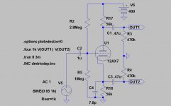
One of the differences must be that the tube has unequal capacitances on both sides. This can be equalized with a small cap between cathode and ground. The schematic is a simmed version of the PaulC mod of a Princeton PI to which I have added C4 to get identical Fu:
Tom Bavis said:The cathodyne is not generally favoured for musical instrument amplifiers, due to the poor overload characteristics.
Tom, I would rather say the opposite: The concertina/cathodyne PI is favoured in a lot of guitaramps just because of its unequal behaviour when overdriven. You find it in Fender Princetons, Tweed deLuxes, Oranges etc.
But both sides have equal Zout (12AX7 has, if I remember it rigth, in the ballpark of 3k). But.... the outputs have different output level capacity with the anode clipping first.
An in depth explanation on how a concertina-PI really works would be welcome.
One of the differences must be that the tube has unequal capacitances on both sides. This can be equalized with a small cap between cathode and ground. The schematic is a simmed version of the PaulC mod of a Princeton PI to which I have added C4 to get identical Fu:
Attachments
An in depth explanation on how a concertina-PI really works would be welcome.
I think the one that is easiest to understand is the one in Morgan Jones book, he also give values of output impedance both for the balanced load case and the unbalanced case i.e if the following stage draws grid current. The Preisman text is also good but much more difficult to understand if you don't have experience of circuit analysis.
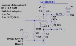
I just did a Spice simulation of a 6SN7 with 15k anode and cathode resistors, it has an output impedance of ~330ohm.
One of the differences must be that the tube has unequal capacitances on both sides
This is described together with the cure already in Valley and Wallman Vacuum tube amplifiers, the say:
Cgk/(Cgk + Cko) should be equal to Gm*R/(1+Gm*R) where Cko is the cathode to ground capacitance, they also say that in order to fulfill this you need to add more Grid-Cathode capacitance.
Regards Hans
tubetvr said:
They also say that in order to fulfill this you need to add more Grid-Cathode capacitance.
Regards Hans
Sorry Hans,
Go back to your 6SN7-sim this and you will find it completely wrong in this case
") ! Tried adding G-Ccap at first but cathode to ground is the only way to make compensation work.
! Tried adding G-Ccap at first but cathode to ground is the only way to make compensation work.:EDIT: I was wrong! Did a sim on your 6SN7-circuit(with 220k load) to verify and if you use a ca 10x higher G-Ccap(78.6p) than G-Groundcap (8.27p) you get about the same result.
Do you have the Preisman paper?
We have had a very interesting discussion about concertinas from guitaramps point of view(not so technically deep though) at:
http://www.ljudbojen.se/bojen/topic.asp?TOPIC_ID=13519
This is a little OT but this one, that I will soon try IRL, has 50ohm Zout, -3dB below 0.1Hz and very little risk of being overdriven
Attachments
Sorry Hans, Go back to your 6SN7-sim this and you will find it completely wrong in this case
Could be, I only quoted from Valley and Wallman from memory but I never have tried it myself, it is often not needed to add any compensation as the poles created by the phase splitter output impedance are so high up, e.g in my OTL the poles are at about 3MHz and has a minor impact on the overall frequency response.
When I read from Valley Wallman the exact text is Quote: "This requirements usually necessitates adding grid-cathode capacitance" end quote, meaning that is usually but not always the case.
There is a link to the Preisman paper earlier in this thread, here it is http://www.aikenamps.com/cathodyne.pdf
Regards Hans
I remembers reading in Morgan Jones's Valve Amplifiers that a concertina splitter (or an LTP splitter, for that matter) is suitable only to feed a following PP stage in Class A, because the loads must be equal. This implies that it should not be used directly to drive Class AB1 or B1 stages, even though these do not draw grid current.
I can't understand this, because I don't see how the load changes if grid current isn't drawn. Class AB2 or B2, sure, they need very low impedance drive anyway to supply the required grid current, but why do AB1 and B1 give uneqal loading? Can anyone enlighten me please?
I can't understand this, because I don't see how the load changes if grid current isn't drawn. Class AB2 or B2, sure, they need very low impedance drive anyway to supply the required grid current, but why do AB1 and B1 give uneqal loading? Can anyone enlighten me please?
- Status
- This old topic is closed. If you want to reopen this topic, contact a moderator using the "Report Post" button.
- Home
- Amplifiers
- Tubes / Valves
- The Valve Wizard