Loads of people in the past have asked about wiring up the chipamp.com PSU boards for use with a center tap transformer. While these threads have been helpful, I want to check I have the right idea before I mod the boards. Most of the threads I have found keep the dual bridge nature of the supply - something that I don't really want to do.
The original PSU schematic can be found here:
http://www.chipamp.com/images/ps.gif
My proposed modification to the schematic is this attached. It is meant to change the power supply to a single full bridge supply. Can somebody check it and tell me if it's going to work as I expect it to?
The original PSU schematic can be found here:
http://www.chipamp.com/images/ps.gif
My proposed modification to the schematic is this attached. It is meant to change the power supply to a single full bridge supply. Can somebody check it and tell me if it's going to work as I expect it to?
Attachments
Thanks AndrewT, that's good to know.
") I will take photos when I receive the boards and have made the required mods.
I will take photos when I receive the boards and have made the required mods.
I can't take a photo, because I don't have the boards yetdanielwritesbac said:Howabout a photo?
I will take photos when I receive the boards and have made the required mods.Okay, Howabout a nicer photo?
The photo was for you, not for me. I don't need a photo of this because I already have one.
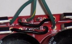
P.S. With CT transformer, the ground hookup at the amplifier is marked "CG"
The ground lead for chassis is, instead, at the tail end of the power supply (see the bridge between PG in photo below).
The ground lead for signal input goes only to source device(s).
The ground lead for speaker goes only to speaker.
See photo--this photo.
The photo was for you, not for me. I don't need a photo of this because I already have one.
P.S. With CT transformer, the ground hookup at the amplifier is marked "CG"
The ground lead for chassis is, instead, at the tail end of the power supply (see the bridge between PG in photo below).
The ground lead for signal input goes only to source device(s).
The ground lead for speaker goes only to speaker.
See photo--this photo.
Attachments
Oh, thanks - sorry I misunderstood.
You seem to be using eight diodes, instead of the four that would be required for a single full bridge. I assume this is because you are using dual bridges. What was your reason for choosing such a configuration? Was it just to minimize changes to the board?
You seem to be using eight diodes, instead of the four that would be required for a single full bridge. I assume this is because you are using dual bridges. What was your reason for choosing such a configuration? Was it just to minimize changes to the board?
cabbagerat said:Oh, thanks - sorry I misunderstood.
You seem to be using eight diodes, instead of the four that would be required for a single full bridge. I assume this is because you are using dual bridges. What was your reason for choosing such a configuration? Was it just to minimize changes to the board?
I'm using 4 diodes. It was helpful for me to download the MUR860 manual and mark the customary stripe on them with the paint marker. I also sat down and sketched the circuit with pencil and paper.
My use of it corresponds somewhat with the directions given on the earlier LM3875 kits. That manual could be at audiosector.com.
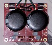
If you click on the two photos (above), they will enlarge.
EDIT: Note that the two halves of the ground (+pgnd & -pgnd) are tied together at both ends of the board. That forms the "just one wire" for CG, common ground of the power supply, corresponding to a hookup point by the same name, on the amplifier boards.
I described it here as well: http://www.diyaudio.com/forums/showthread.php?postid=1196283#post1196283
- Status
- This old topic is closed. If you want to reopen this topic, contact a moderator using the "Report Post" button.
- Home
- Amplifiers
- Chip Amps
- Chipamp.com PSU with CT transformer