Hi Folks,
Need a little help with this schematic. Simple question I believe.
Concerning the power supply caps as circled in the schematic - Although not marked on the circuit diagram, I presume that these are electrolytic caps with the positive side closest to the choke?
Can anyone just confirm this for me. I have asked a similar question abut this schematic - it just seems a little sloppy (by that I mean non-precise) to me but I can't find any other.
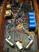
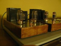
I have just had the chassis made and am hoping to post a completed amp within the next month or so. I am making a stereo version of the mark 3 from the ground up - probably should have made a couple of monoblocks, did not really appreciate how much this thing was going to weigh!
Cheers,
Rob
Need a little help with this schematic. Simple question I believe.
Concerning the power supply caps as circled in the schematic - Although not marked on the circuit diagram, I presume that these are electrolytic caps with the positive side closest to the choke?
Can anyone just confirm this for me. I have asked a similar question abut this schematic - it just seems a little sloppy (by that I mean non-precise) to me but I can't find any other.
I have just had the chassis made and am hoping to post a completed amp within the next month or so. I am making a stereo version of the mark 3 from the ground up - probably should have made a couple of monoblocks, did not really appreciate how much this thing was going to weigh!
Cheers,
Rob
Attachments
they have used that symbol for all of the caps, including the non-polarized ones!
Not only that, but 50 uF caps for the negative bias supply are shown with the + symbol in the correct place, but the curved line in the wrong place.
Oh, well. Hopefully they had good assembly drawings when they built these, and not just the schematic.
Hi Robert,
Well I think that a lot of the guts of the amp was built onto a preassembled circuit board, so that obviously made the schematic a little less critical. However, 50 years down the track and I am building this from the circuit diagram alone, so little inaccuracies have the potential to mess things up for me. Thanks for the help.
Rob
Hey Rob,
My sounds darn good. Couple of pointers in case you don't know it already:
1] For the power supply caps (which you circled) try to stick to the values or close to the values shown. Larger capacitance doesn't do any good with the tubes... those caps (single or multiple of) should be rated higher than 600VDC.
2] the .25uF coupling caps depending on the type does alter the sound of the amp. I ended up with jensen oil/paper caps for smoothness.
Please post your amp when you are done.
Cheers,
Norm
Hi Norm,
Thanks for the advice. Actually, the only kit part I am using is an SDS power caps board for the mark 3 which you may have seen. It uses 400v 100uf caps in series to achieve the capacitance and voltage ratings required. I was going to use sprague atoms but I only have 5 x 600v 20uf caps and no 30uf which I had trouble sourcing at the 6oov rating. For the coupling caps I am using some big sprague 0.22 uf orange drops. Hope the SDS caps board is OK - the overall capacitance is higher than rated as is the voltage but they are supposed to be OK. Maybe I should have tries harder to find some 30uf atoms.....
Rob
The first cap (the one between the rectifier tube ad choke) should not be higher than 40uF. Having said that I was running at 50uF for a while and didn't hear any thing different other than had to replace the rectifier tubes couple of times, not sure if its related. I have since changed it to 38uF and will keep an eye for the rectifier longevity.
Norm.
Norm.
- Status
- This old topic is closed. If you want to reopen this topic, contact a moderator using the "Report Post" button.
- Home
- Amplifiers
- Tubes / Valves
- Help with Schematic