where to buy parts (transformers and chokes)
i am building a tube amp for a college project,,
consequently time is of the essence.
i have found sources for most components, but i cant find a decent supplier of transformers and chokes for valve amps.
if any of you know of any decent suppliers of tube amp parts (preferably as close to the uk as possible) please let me know.
cheers
soundbadger
Hello soundbadger,
I have had great success w/ Electra-Print iron. I believe the quality is second to none, and you get the added bonus of a transformer tutorial when you get Jack Elliano on the phone. If you're not exactly sure what you need, he'll even figure out what's best for your application. Sharp guy, very helpful, and a superb product. I know Las Vegas isn't close to England, but with the pound/dollar ratio what it is, the prices should be very favorable.
Good luck w/ your project.
Cheers, Crazy Bill")
I have had great success w/ Electra-Print iron. I believe the quality is second to none, and you get the added bonus of a transformer tutorial when you get Jack Elliano on the phone. If you're not exactly sure what you need, he'll even figure out what's best for your application. Sharp guy, very helpful, and a superb product. I know Las Vegas isn't close to England, but with the pound/dollar ratio what it is, the prices should be very favorable.
Good luck w/ your project.
Cheers, Crazy Bill
Hi !
I know nearly all output-transformer-dudes on the planet.
In the UK there are:
Majestic Transformer
Living-in-the-past
Sowter
Variable Voltage Technology
HIFI Collective (Glasshouse & Audio-Note Transformers)
Think that was all.
I Hope I could help you
Regards, Simon
PS: Du to that low $$$ it is a very good chance to buy in the USA. One Pound ~ 2$ ! You will get these Hammonds and Edcors dirt cheap !
hello there
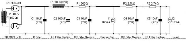
i have designed a power supply using psud2 (see attached jpg) , it is to power 2 kt88 tubes and 2 pre-amp tubes (undecided on exact type), i just wondered if someone could take a look and tell me what they think. is there anything i should do differently. i need a power supply to give 2 different voltages for the power and preamp tubes this seemed the easiest way.
the transformer resistance of 150r is just a guess but the chokes 82r is a hammond 193j.
any help appreciated,,,,
soundbadger
UK toroidal power transformers
I've got plenty of toroidal power transformers for sale:
http://www.ax84.com/bbs/index.php?id=321421
I've got plenty of toroidal power transformers for sale:
http://www.ax84.com/bbs/index.php?id=321421
hello there
i have designed a power supply using psud2 (see attached jpg) , it is to power 2 kt88 tubes and 2 pre-amp tubes (undecided on exact type), i just wondered if someone could take a look and tell me what they think. is there anything i should do differently. i need a power supply to give 2 different voltages for the power and preamp tubes this seemed the easiest way.
the transformer resistance of 150r is just a guess but the chokes 82r is a hammond 193j.
according to psud this circuit provides 410v at 160mA and 345v at 12mA
any help appreciated,,,,
soundbadger
Attachments
So this is a single ended amp?
If it were me, I'd remove R1 and C3. If you are aiming for a specific ripple at the output stage, increase C2 as needed. Look at the current through L1; make sure it doesn't go near zero for all operating conditions.
Do you have any requirements for ripple on the preamp stage? If it doesn't have to be extremely low, you could also replace the RCRC with a single RC.
i had thought about replacing the rcrc with a single filter.
but with regards to removing r1 and c3 the ripple going to the power tubes (the 160mA current tap) is higher than i would like when i just use the c-l-c which is why i added the extra r-c.
is this acceptable, / would you have done it differantly ,,
as always any advice greatly appreciated
cheers
soundbadger
oh and yes it is an SE amp design
Well, I see very very little difference in ripple between C2-C3 and C4-C5.
C2 measures 395V with 47mV ripple.
C3 measures 360V with 25mV ripple. Not extremely different, and you ended up adding 200 ohms of resistance in series with the bulk storage of your output stage to reduce ripple by half. The actual output stage essentially has only 10uF to work with; the rest comes from a high impedance source; not good practice for an output stage.
If 360V is your target, I would place something like a 4uF cap for C1 and 200uF cap for C2. Any resistance to tweak your output I would add immediately after the tube rectifiers, and it doesn't need to be much.
Similar with C4 and C5, one stage might be better with a 20uF cap. Extremely low ripple would require another choke. Up to you.
Most importantly, you need to model your transformer correctly in order for PSUD to predict correct output voltages. Do you actually have the xfmr?
The actual output stage essentially has only 10uF to work with; the rest comes from a high impedance source; not good practice for an output stage.
This is true. It will cause your frequency response to become non-linear as that 200 ohm resistor will become part of the output stage. When frequency drops below where the 10uF(C3) cap becomes effective.
If it were me, I'd remove R1 and C3. If you are aiming for a specific ripple at the output stage, increase C2 as needed. Look at the current through L1; make sure it doesn't go near zero for all operating conditions.
I'd have to agree.
- Status
- This old topic is closed. If you want to reopen this topic, contact a moderator using the "Report Post" button.
- Home
- Amplifiers
- Tubes / Valves
- power supply PLEASE HELP