ok, so a friend of mine is running his amp at 1/2 ohm for quite a while (amp is rated for 1 ohm min, I advised him it would blow up sometime soon and it did. hah. ) 
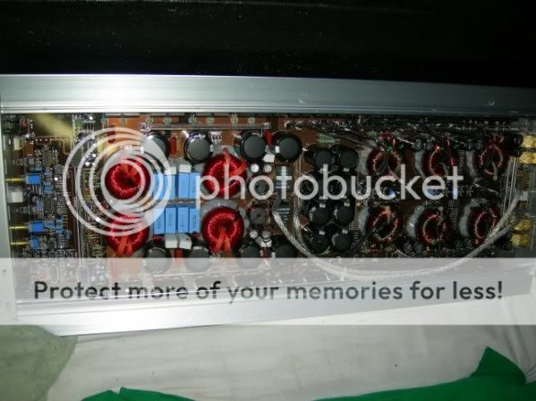
this is the same amp in ampguts ROE Digital Designs M1
ok, so it blew all power supply fets (85N06 x8pcs) , one IRF9640N and one IRF640N. the IRF parts are on the amp section output stage.
I haven't tested the drivers for the supply and amp fet drivers but there are no shorts (slight blackening of the 22R gate resistors for the SMPS fets but still measure ok) so I think they should hopefully still work. didn't have access to my scope when we took it apart. going to use the scope when I get to the other house.
I question the availability of the SMPS fets so what can be an alternative? (85A 60V)
also, I know it would be wise to replace ALL output devices to have proper current sharing. how necessary is this? the 9640 is independent of the other 9640's but the '640 is paralleled to another two. so that means I have to replace three in all for proper current sharing?
here's the schematic (very simplified) of the output stage so you can understand what I'm saying. the 'slashed' fets are the blown ones.
supplies are independent but equal in voltage.
also, is it advisable to run the amp WITHOUT output stage fets installed to see if the driver/modulator board works?
this is the same amp in ampguts ROE Digital Designs M1
ok, so it blew all power supply fets (85N06 x8pcs) , one IRF9640N and one IRF640N. the IRF parts are on the amp section output stage.
I haven't tested the drivers for the supply and amp fet drivers but there are no shorts (slight blackening of the 22R gate resistors for the SMPS fets but still measure ok) so I think they should hopefully still work. didn't have access to my scope when we took it apart. going to use the scope when I get to the other house.
I question the availability of the SMPS fets so what can be an alternative? (85A 60V)
also, I know it would be wise to replace ALL output devices to have proper current sharing. how necessary is this? the 9640 is independent of the other 9640's but the '640 is paralleled to another two. so that means I have to replace three in all for proper current sharing?
here's the schematic (very simplified) of the output stage so you can understand what I'm saying.
the 'slashed' fets are the blown ones.supplies are independent but equal in voltage.
An externally hosted image should be here but it was not working when we last tested it.
also, is it advisable to run the amp WITHOUT output stage fets installed to see if the driver/modulator board works?
I'd remove the defective outputs and power it up (watching carefully for excessive current draw and other problems).
With the output transistors removed, you're not likely to have any switching output. Removing the outputs will leave the feedback loop open so the output of the driver board will likely be DC.
For equal current sharing, you need to replace all of the FETs that were in the group (even if they were driven by different outputs from the driver board). In this amp, I'd suggest replacing all of the outputs. They've all be subjected to the same abuse. It's possible that the remaining ones are not 100%. There's no point in taking a chance of destroying the power supply again if one of the original outputs fails.
I'd use an IRFP064 if the originals were not available.
When some amps go down, they take out everything but the rectifiers and the regulators.
Hopefully, the driver board survived. I couldn't tell from the photo but it looked like the driver uses discrete surface mount transistors for the output. That will make it easier/less expensive to repair.
Before you pull all of the good outputs, solder a couple of FETs (anything will be good enough for testing) in each power supply to see if the output section works properly (with the defective FETs removed). You may want to move one of the paralleled FETs to the isolated position to be sure that the drive circuit for the failed FET is still working properly. Then, after you find all of the problems and know 100% that you'll be able to repair it, you can order the parts.
Your friend can't complain. You warned him. Next time you warn someone, let them know how much it's going to cost to repair. That seems to help convince them... sometimes.
DD amplifier
If a Mosfet is good why replace it. If you do not know how to test for bad devices, then of course it is easier to repalce all. Current sharing is non existent, as these Korean ,ade class Ds certainly do NOI match Mosfets for any reason. And do you know why, because a class D amplifier is simply a switching power supply which has been modulated by audio. Switching supplies need no matching. The Mosfets do not work in their linear area, they are either on or off.
Simp,est way to check is to have at least one good out put device in both power supply and class D amplifier on all push pull sections (Yes the class D is a half bridge design with 4 sections of output devices and coils are "orred" together (we have repaired so many of these generic class D amps).
So you will need for audio Mosfets and depending how they configured their supply it may also be in two separate push pull sections then at least 4 devices.
Power the amplifier with a series 4 ohm 30-50w limiting resistor and watch the power supply waveform on a scope. You need power supply knowledge to know waht to look for. At the same time monitor the speaker output and drive the amplifier with a 50-100Hz sinewave
If you get the +/-Vcc supplies correct (lower than normal due to 4 ohm limiting resistor) and the sinewave looks OK on a scope, then safe to say that all would be well.
Then put in the balance of all Mosfets.
These Korean amplifiers are NOT safe into 1 ohm loads as the class D output stage suffers from common conduction (shoot through) and they die quickly
Steve Mantz
Zed Audio Corp.
I don't agree that the FETs don't need to be matched. The threshold may not need to match but the RDSon needs to be virtually identical.
Even if they don't need to be matched (again, I don't agree), the ones that survived were subjected to the same abuse as the ones that failed. There's no guarantee that they're 100%.
I've seen lots of FETs that had solder forced out of them (between the tab and the plastic housing) and they checked OK with a multimeter. I certainly wouldn't have reinstalled them. Just because they check Ok with a multimeter, that doesn't mean they are good enough to be re-used. It's not good practice to re-use parts that have seen abuse.
well, I checked the powersupply control board and the fet drivers are toast. but the KA7500 chip still sends out a PWM signal and the muting relay clicks so it looks like only the drivers died. these are discrete so they can be replaced. although they are SMD. I have no problem working with SMD's, they're just unobtanium over here.
good idea with substituting other fets on the supply just to see if the class D controller still works. will do that soon when I get the SMPS controller board running.
I always use a headlight bulb in series with the B+ supply to limit current during initial testing.") minimizes the chance of letting more magic smoke out. hehehe
minimizes the chance of letting more magic smoke out. hehehe
as for testing the other output stage fets, I connected a load to its drain and applied a small DC voltage to the gate by touching it. hard to describe how I did it but I'm sure there's no ESD risk there. the fets tested OK and switched the load no problem with just the resistance of my fingers.
good idea with substituting other fets on the supply just to see if the class D controller still works. will do that soon when I get the SMPS controller board running.
I always use a headlight bulb in series with the B+ supply to limit current during initial testing.
minimizes the chance of letting more magic smoke out. heheheas for testing the other output stage fets, I connected a load to its drain and applied a small DC voltage to the gate by touching it. hard to describe how I did it but I'm sure there's no ESD risk there.
the fets tested OK and switched the load no problem with just the resistance of my fingers. I can't find the edit button.
oh well,
I forgot to mention a few things.
the SMPS controller output is pulled up by the open collectors of the KA7500 (similar to TL494) and pulled down by the discrete transistors. those transistors get really hot when the amp is powered up without the fets. I haven't noticed but the chip doesn't seem to get hot. at most, it's probably getting warm but as I said, I didn't notice. only did a quick check. hehehe
the class D controller outputs are totem poles. all six of them (three for each half bridge) so I was wondering, if a totem pole dies, does it also take out something upstream?
::::update::::
I substituted temporary IRFZ34/44 fets on the powersupply after replacing a pair of driver transistors on the SMPS controller board (didn't have SMD SOT89 parts available so I used japanese parts that had the same BCE pinout and dropped it in and it worked)
to make sure the drivers can handle the high gate charge of the supply fets, I temporarily soldered a pair of 47nF caps on the gate-source terminals and the drivers can push a nice square wave (26.3kHz) into that load so hopefully it will do.
I haven't looked for FQP85N06 fets (TO-220) over here but IRF3205 looks like a good candidate? -----
I filled up the empty output stage fet places and powered it up.
with a 13V input, we get +/- 68V rails.
I connected my scope to the half bridge output (just before the LC output filter) and got nice square waves ( 142.8kHz) on both sides and no DC offset on the speaker terminals with no load.
input current on the B+ line is around 1.7A idle with no load connected.
I haven't tested it by applying a signal yet but I'm assuming it will work.
any more tips to consider??
just wanna update you guys.
after a while of looking for the right supply fets, I wasn't able to find some. seems like they discontinued IRF3205? it's become very hard to find them here.
so what I did was buy eight IRFZ44's and used them to replace the eight IRF3205's in my DIY car amp (that was way way over engineered for a 200w /ch amp) and used the old fets on the DD M1.
tested it on my 15" dual 2ohm sub and pounds like hell. will be using it for a while before I return it to the owner to make sure it won't blow up.
so, what I replaced was:
6pcs IRF640
6pcs IRF9640
8pcs 85N06 to IRF3205
8pcs 22R gate resistors
2pcs SMD gate drive transistors.
luckily, no major component or really really hard to find part blew.
- Status
- This old topic is closed. If you want to reopen this topic, contact a moderator using the "Report Post" button.
- Home
- General Interest
- Car Audio
- blown Digital Designs M1 mono amp