I was having an email conversation with someone who mentioned that, w/r/t/ transformer coupled grounded cathode circuits, they generally used fixed bias, and that they disliked the Ultrapath circuit. This got me to thinking about the differences between these two circuits.
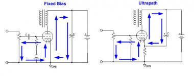
I looked back at the slides from Lynn Olson from the 2004 ETF where he traces current paths in various amplifiers, and drew a similar diagram for a fixed bias circuit.
I was struck by two things. First, Lynn's schematic does not match Elliano's, and that the consequence of this seems to be that Lynn has an additional cap in the signal path (the original has a resistor between the Ultrapath cap and the previous power supply cap.) Second, and more importantly, the fixed bias circuit has the same path for the output current, but adds a capacitor to the input. Now, presumably as this can be a tiny little 0.1uF cap it is pretty harmless all things considered.
I am wondering what other advantages fixed bias might have to elicit such a strong reaction. Clearly, the input current can marginally influence the operating point of the tube as it changes the bias of the tube by altering the current that flows through the bias resistor, but is this enough to be worse than another cap? Any other thoughts?
Attachments
dsavitsk said:I was struck by two things. First, Lynn's schematic does not match Elliano's, and that the consequence of this seems to be that Lynn has an additional cap in the signal path (the original has a resistor between the Ultrapath cap and the previous power supply cap.) Second, and more importantly, the fixed bias circuit has the same path for the output current, but adds a capacitor to the input. Now, presumably as this can be a tiny little 0.1uF cap it is pretty harmless all things considered.
I am wondering what other advantages fixed bias might have to elicit such a strong reaction. Clearly, the input current can marginally influence the operating point of the tube as it changes the bias of the tube by altering the current that flows through the bias resistor, but is this enough to be worse than another cap? Any other thoughts?
That additional resistor in the Eliano circuit provides some isolation from the previous power supply cap, but the degree is dependant on the value. So it can vary from just a little to quite a lot, but never complete.
One advantage of fixed bias for the DIY'er is a practical one - it's easy to design the bias supply to be adjustable, which in turn makes it easy to change the operating point of the tube or even the tube type. A second practical advantage of fixed bias, is that it doesn't waste power supply voltage heating the cathode resistor. Two disadvantages are that it requires a bias supply, and that the operating point of the tube can wander quite a bit if the line voltage is not stable and the supply is not regulated. If the tube is run near its maximum rating this would have to be taken into account for reliability. If the B+ supply is not regulated, some compensation will be effected if the bias supply is also not regulated (so regulate both or neither).
I think the input current through the cathode circuit is a non issue (or at least waaay down the list) for anything but class A2 applications, where the grid current can be significant and will add to the plate current. For that situation, fixed bias or led bias (or some other low impedance constant voltage source) would be the obvious choice.
Sheldon
Re: Re: Fixed Bias v Ultrapath
But then, of course, you have an LED or a battery in the input and output signal path. Now, I have been a pretty big proponent of the LED bias method, but I am becoming a little less convinced that it is necessarily better than a good cap, and especially if that cap can be a tiny cap on the input instead of a big one on the cathode -- though it is certainly cheaper.
Anyhow, clearly the ultrapath's main problem is that the PS must be quieter by a factor of mu which is often unachievable with high mu valves.
That's interesting, and would seem to be for the same reason that a single cap in the PS is not sufficient to short circuit all of the PS ripple -- so it would seem that this works best with a lowish cathode resistor and a high-ish PS resistor can be used, or perhaps a choke.
I would think so.
Anyhow, I don't think I am a proponent of either of these -- I just though the similarity in the output paths was interesting.
rdf said:Fixed bias doesn't always require an input cap. Using the left hand example, move the bias supply to the tube's cathode and voila, fixed bias with, depending on the architecture of the bias supply, one less cap. One example replaces the cathode supply with an LED.
But then, of course, you have an LED or a battery in the input and output signal path. Now, I have been a pretty big proponent of the LED bias method, but I am becoming a little less convinced that it is necessarily better than a good cap, and especially if that cap can be a tiny cap on the input instead of a big one on the cathode -- though it is certainly cheaper.
Anyhow, clearly the ultrapath's main problem is that the PS must be quieter by a factor of mu which is often unachievable with high mu valves.
Sheldon said:
That additional resistor in the Eliano circuit provides some isolation from the previous power supply cap, but the degree is dependant on the value. So it can vary from just a little to quite a lot, but never complete.
That's interesting, and would seem to be for the same reason that a single cap in the PS is not sufficient to short circuit all of the PS ripple -- so it would seem that this works best with a lowish cathode resistor and a high-ish PS resistor can be used, or perhaps a choke.
Sheldon said:I think the input current through the cathode circuit is a non issue (or at least waaay down the list) /B]
I would think so.
Anyhow, I don't think I am a proponent of either of these -- I just though the similarity in the output paths was interesting.
Re: Re: Re: Fixed Bias v Ultrapath
I'm not arguing for or against any topology either, and I'm not one of those who have capophobia. Personally, I can't usually hear a big difference between one good quality cap and another. And if I hear a difference it may not be a better/worse thing. But if a cap can be dispensed with, why not?
I would like to point out that the ultrapath cap is still very much in the signal path. Yes, unlike a regular cathode bypass cap, it does serve as the final ps cap and presents an antiphase noise signal to the cathode, in the bargin (I do think that cancellation can be a rather elegant solution to ps noise management). But it still functions as a bypass capacitor to shunt AC signal via a low impedance path to common. So it's directly in series with the signal. An interesting variable here is that the impedance of that path in the UP connection, obviously depends on the power supply, and that would affect the sonics as compared to the regular cathode cap.
Sheldon
dsavitsk said:But then, of course, you have an LED or a battery in the input and output signal path. Now, I have been a pretty big proponent of the LED bias method, but I am becoming a little less convinced that it is necessarily better than a good cap, and especially if that cap can be a tiny cap on the input instead of a big one on the cathode -- though it is certainly cheaper.
I'm not arguing for or against any topology either, and I'm not one of those who have capophobia. Personally, I can't usually hear a big difference between one good quality cap and another. And if I hear a difference it may not be a better/worse thing. But if a cap can be dispensed with, why not?
I would like to point out that the ultrapath cap is still very much in the signal path. Yes, unlike a regular cathode bypass cap, it does serve as the final ps cap and presents an antiphase noise signal to the cathode, in the bargin (I do think that cancellation can be a rather elegant solution to ps noise management). But it still functions as a bypass capacitor to shunt AC signal via a low impedance path to common. So it's directly in series with the signal. An interesting variable here is that the impedance of that path in the UP connection, obviously depends on the power supply, and that would affect the sonics as compared to the regular cathode cap.
Sheldon
So far my ears (and meters) have voted for the LED. I believe Olsen's vote differently. To be an annoying stickler, it's perfectly valid to bypass the cathode LED with a cap and bench tests show it greatly reduces the harmonics generated by the cathode load. It's just my preference so far to avoid caps.
One thing that can be said for the LED, the loops don't change with frequency. I think the diagrams posted take some liberties. At lower frequencies where the impedance of the smoothing and UP caps approach those of the transformer and any PS choke things must get more complex, especially with UP. There should really be two output loops. Looking at it closer still made me realize something else that bothers me. The diagrams treat all devices in the loops as equal without consideration to each device's impedance and the resultant 'error' voltage generated. Even that's not true, both appear comfortable ignoring the grid resistors but including the orders of magnitude higher grid impedance in the loops. So while I understand the intent of these loop diagrams the specific logic behind the choices escapes me. How do they justify ignoring the grid battery for example?
One thing that can be said for the LED, the loops don't change with frequency. I think the diagrams posted take some liberties. At lower frequencies where the impedance of the smoothing and UP caps approach those of the transformer and any PS choke things must get more complex, especially with UP. There should really be two output loops. Looking at it closer still made me realize something else that bothers me. The diagrams treat all devices in the loops as equal without consideration to each device's impedance and the resultant 'error' voltage generated. Even that's not true, both appear comfortable ignoring the grid resistors but including the orders of magnitude higher grid impedance in the loops. So while I understand the intent of these loop diagrams the specific logic behind the choices escapes me. How do they justify ignoring the grid battery for example?
rdf said:At lower frequencies where the impedance of the smoothing and UP caps approach those of the transformer and any PS choke things must get more complex, especially with UP.
So while I understand the intent of these loop diagrams the specific logic behind the choices escapes me. How do they justify ignoring the grid battery for example?
I had wondered about the effect at lower frequencies too. The ultrapath caps I've seen in most of the schematics give a fairly high cut off - sometimes around 20Hz or so - at least higher than I see for cathode bypass. With a power supply that has significant impedance behind the ultrapath cap - for instance, the one shown with a resistor - it seems the cap could act a bit like a boostrap.
I agree that the loop diagrams seem arbitrary as to defining the loops.
Sheldon
- Status
- This old topic is closed. If you want to reopen this topic, contact a moderator using the "Report Post" button.
- Home
- Amplifiers
- Tubes / Valves
- Fixed Bias v Ultrapath