Hi Roe,
the standard Leach uses four diodes in the resistor string and I have found it is overcompensated for temperature.
The four output devices are ideal for supplying the four compensating diodes, but I fear he will find that bias becomes too low as the sink heats up. It will be very difficult to keep Vre between 15mV and 25mV for all operating conditions.
How could we alter the compensation? add a diode in the lower leg? or add a resistor in the emitter side of the Vbe?
Interesting. I see a few curious features here. Not criticizing, just curious:
Is the offset adjustment and regulated front-end necessary for a leach amp? I understood it wasn't really needed.
Are 50v decoupling caps enough for the +/-58v front end?
Is the input cap a large enough value? I usually see much larger values than this. I'd even use a film cap there if 3-5uF is suitable.
..Todd
AndrewT said:Hi Roe,
the standard Leach uses four diodes in the resistor string and I have found it is overcompensated for temperature.
The four output devices are ideal for supplying the four compensating diodes, but I fear he will find that bias becomes too low as the sink heats up. It will be very difficult to keep Vre between 15mV and 25mV for all operating conditions.
How could we alter the compensation? add a diode in the lower leg? or add a resistor in the emitter side of the Vbe?
Hi Andrew
The TC for a NJL diode is 1.66V/C at 2 to 4mA forward current. Output stage of Leach amp has 6 serial Vbe with TC 2 ... 2.1mV/C each.
Make the math, please!
Hi Roe,roender said:......The TC for a NJL diode is 1.66V/C at 2 to 4mA forward current. Output stage of Leach amp has 6 serial Vbe with TC 2 ... 2.1mV/C each.
are you saying that the integrated diodes are very different from external diodes?
I have measured my Leach clone and 4diodes definitely overcompensates. When Leach changed from three diode compensation he says he did so simplyto bring the diode leads back to the same side of the heatsink so that connecting back the the circuit board was easier. He reckoned three diodes were sufficient.
I suspect you have noticed that the diodes are inside the Vbe multiplier loop.
Yes triple stage EF has 6BE junctions effectively in series. One of the main advantages of this topology is the very low loading on the earlier stages. The output devices will vary in temperature. Two diode compensating junctions should be about right. The drivers hardly change in temperature. They run at near constant 500mW to 1000mW (depending on Re) irrespective of transient output currents. Partial compensation could be sufficient here. That could probably be met with one more BE drop.
The pre-drivers probably vary no more than a few tens of Cdegress from cold start up to high ambient temperature. No compensation is probably required. That senario would probably explain why my 4diode build over compensates.
The best results are achievable when all 6 BE junction are thermally coupled. Then, you have to do the math, if you know TC for all forward biased junctions at working currents.
This is my latest amp with ThermalTrack BJT's on output stage. It has only -5mV drift over Re's from 20 to 70grdC. I have 4 BE series junctions on the output stage, 2 on CFP driver and 2 on output BJTs and 5 NJL diodes used to compensate thermal drift.
http://www.diyaudio.com/forums/attachment.php?s=&postid=1313491&stamp=1191162639
http://www.diyaudio.com/forums/showthread.php?postid=1313489#post1313489
The relationship between forward-biased BE junction and internal diode in a ThermalTrack BJT is presented in the following figure
http://www.diyaudio.com/forums/showthread.php?postid=1282579#post1282579
http://www.diyaudio.com/forums/showthread.php?postid=1282579#post1282579
The latest Leach amp (4.5) has 3 diodes for biasing. If I will try to build a clone with double pair of thermaltraks and use all 4 diodes I would be very near the same compensation as the original one, am I right?
roender , I know you have tried the thermaltraks from the roender - symasym thread and also your latest project, but if I understand you right you say its not possible to build an amplifier with two pairs using thermaltraks?
Please enlight me")
roender , I know you have tried the thermaltraks from the roender - symasym thread and also your latest project, but if I understand you right you say its not possible to build an amplifier with two pairs using thermaltraks?
Please enlight me
Hello
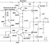
I only founded four NJL0281 and four NJL0302 , so the thermal track Leach's VBE would have less diodes.
I'm making my own amp, using a CFP driver output, can a single transistor vas would work good with a CFP driver output ?
Here is the cfp drivers output schematic, it's not tweaked but it's near final, is my CFP driver thermal track output are ok ?
Thank
Bye
Gaetan
Attachments
Hi Gaet,
the 0r15 is far too low. It will overheat the MJE drivers.
I would still use 4diodes (1 from each output) but you may want to experiment with adding a small resistor value to the emitter of the BD139. Someone symmed this recently and reported good results.
Have you looked at the interview threads - fets includes a section on using diode compensation?
Hi Gaetan,
With only 4 diodes output stage will be undercompensated and on a verge of runaway:
4*(-1.66) = -6.64 mV/K Total TC for NJL diodes.
4*(-2.1m) = -8.4mV/K Total TC for drivers (CFP) and output BJTs BE junctions.
The output stage will have a total TC = -2.24mV/K !!!!!
You need five NJL diodes with total TC = 8.3mV/K
Mihai
AndrewT said:Hi Gaet,
the 0r15 is far too low. It will overheat the MJE drivers.
I would still use 4diodes (1 from each output) but you may want to experiment with adding a small resistor value to the emitter of the BD139. Someone symmed this recently and reported good results.
Have you looked at the interview threads - fets includes a section on using diode compensation?
Hello Andrew
I want to keep the drivers allway ON in class A, to minimize switching noise, so what would be the minimum value to replace the 0r15 resistor ?
How about 50 ohm for small resistor value to the emitter of the BD139 ?
You mean to look at the "Bob Cordell Interview: BJT vs. MOSFET" ?
Thank
Gaetan
roender said:Hi Gaetan,
With only 4 diodes output stage will be undercompensated and on a verge of runaway:
4*(-1.66) = -6.64 mV/K Total TC for NJL diodes.
4*(-2.1m) = -8.4mV/K Total TC for drivers (CFP) and output BJTs BE junctions.
The output stage will have a total TC = -2.24mV/K !!!!!
You need five NJL diodes with total TC = 8.3mV/K
Mihai
Hello Mihai
Can I ad a 1N4148 for the fifth diode ?
Thank
Gaetan
gaetan8888 said:
watt would be the minimum value to replace the 0r15 resistor ?
Thank
Gaetan
15ohm will bias drivers at 75mA
gaetan8888 said:
Hello Mihai
Can I ad a 1N4148 for the fifth diode ?
Thank
Gaetan
No, use a MUR120. Put all output stage junctions on the same heatsink ... take a look at RMI-FC100 thread. Or use three NJL pairs
roender said:
No, use a MUR120. Put all output stage junctions on the same heatsink ... take a look at RMI-FC100 thread. Or use three NJL pairs
Hello Mihai
I have some 1N5819 , can I use that ?
Thank
Gaetan
Radioman62 said:Or you can use a 4 units endstage and just use the diode on a fifth one.
Reason is you only get 5 Pieces of each as sample from ON Semi
Hello
I should do that, as you guess I did get 5 Pieces of each as sample from ON Semi, at least the fifth NJL will be at good use.
They don't have those NJL at Mouser.com but they have the MJL version only.
Thank
Bye
Gaetan
- Home
- Amplifiers
- Solid State
- Leach To Thermal Trak