I don't know whether this was discussed or not. I know two bridge amp configurations. Is third one available? Or even more?
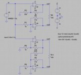
For the two config shown here, which one is better? I simulated them in LTspice. FFT and .FOUR results show that Top one has a lower THD than the bottom one. Is it the whole picture?
For the two config shown here, which one is better? I simulated them in LTspice. FFT and .FOUR results show that Top one has a lower THD than the bottom one. Is it the whole picture?
Attachments
panson_hk said:I don't know whether this was discussed or not. I know two bridge amp configurations. Is third one available? Or even more?
I know at least two more:
- SuperSymmetry by Nelson Pass (google " supersymmetry nelson pass" and " supersymmetry passdiy" and in this forum " supersymmetry lm3886"
AFAIK there are several ICs by Texas Instrument based on Nelson Pass patent
- SSM2142 Balance Line Driver by Analog Devices www.analog.com
Marco
jerluwoo said:The reason your second circuit has higher thd is because the second amp is being fed by the output of the first. There is more distortion from the amp device output being divided and reamplified than there is from being fed by a source like in the first circuit.
i agree with that!
since the output of the inverting amp is taken from the non-inverting stage;aside from the signal,distortion from the non-inv amp is also amplified by the inv stage..in this amp configuration,higher thd is expected.
jerluwoo said:The reason your second circuit has higher thd is because the second amp is being fed by the output of the first. There is more distortion from the amp device output being divided and reamplified than there is from being fed by a source like in the first circuit.
I am not sure now, as the lower amp has a gain of 1, i can't see how it can amplify distortions from the other amp....

Yes one would think it has reduced gain but it actually has the same gain as the top amp. If you measure where the 2 11k's meet the 1k it will show the same amplitude as the original signal being fed to the top amp. So if they are fed the same amplitude signal at the input they must have the same gain in order for the amplitude at the outputs to be the same. If you make the gain of the lower amp 1 then you would need to change both 11k resistors to 1k to achieve the same amplitude at both outputs. The same increased distortion will remain though.
jerluwoo said:Just noticed also that your first example ,both fed from the source, is unbalanced. Top amp has a gain of 10 and the lower 11. This will affect your distortion sims.
yup, in the lower set, to which i commented, all the gain is provided by U1 and U4 is just a unity buffer, this configuration is much better than the upper one..imho...
jerluwoo said:Just noticed also that your first example ,both fed from the source, is unbalanced. Top amp has a gain of 10 and the lower 11. This will affect your distortion sims.
Gain unbalanced, you are right. R7 of the lower bridge amp should be changed to 10 k. Then both amps are of gain 11.
djk said:Is this for a power amp, or a line driver application?
In a power amp the first type in your attachment may have better specs, but is more prone to oscillation.
The second type is less fussy, and is used in amplifiers like the Adcom GFA555.
Hi djk,
Thanks for your sharing. Why is the first one pone to oscillation?
panson
IIRC, the problem was related to current flowing through the load and the diff input of the other half trying to correct it. This would see-saw back and forth as fast as the amplifier would go (in excess of 1Mhz) and could cause common-mode conduction and destroy the amplifier. Many designs deliberately roll-off the HF response (above 200Khz or so, determined by experiment) of one side to help with this.
There was a real good two-part article on bridge amplifiers in Wireless World magazine circa 1980~81.
It would be worth a trip to the library (if yours has the magazine).
Designs for two amplifiers were presented, one was a 20W 12V design, the other a 200W design.
There was a real good two-part article on bridge amplifiers in Wireless World magazine circa 1980~81.
It would be worth a trip to the library (if yours has the magazine).
Designs for two amplifiers were presented, one was a 20W 12V design, the other a 200W design.
- Status
- This old topic is closed. If you want to reopen this topic, contact a moderator using the "Report Post" button.
- Home
- Amplifiers
- Solid State
- Bridge amp config comparison