Am in the process of making a bench PS. (linear regulated)
at the main time am using LM3x7 to do the regulation until
ican find others with more current handling (eg. lm137,lm350..)
my problem is that i cant find a suitable say 24-0-24 3A trans.
so i can get about +36 , 0 , -36 outputs from the 2 regulators.
ques. is can i use 2 x 12-0-12 3A trans. in somehow to achieve
2x 24 rail inputs??
thanks.
subwo1 said:Use one transformer for the positive supply, and the other for the negative. leave the center tap of each open.
Hi,
When you say "open" the centre-tap secondaries must be connected together (although not grounded) to work like this, of course.
Regards,
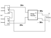
deepanger said:ive connect 2 of the seconderies wires together, and the 2 tap
wires together and use it as the ground, then use the 2 outer
secondries together to feed the rectifier as shown,,
am i right?
Rather like this:
Attachments
Hi,
The way I would do it is, precisely as subwo1 suggested.i.e. use one transformer for +24v and the other for -24v.
However 'terminology' varies and my understanding of secondaries being "open" means completely disconnected, which is not quite correct here.
On all dual secondary transformers (at least all those I have ever seen), there should be 4 secondary wires which will be identified by colour if they are leads, or markings if it has tags.
For each TR there will be two 'starts' to the coils and two 'ends'.
Taking each individual transformer at time, you can connect the two 'starts' together and the two 'ends' together, and you will then have the same voltage (12v, in your case) across these two leads, but the TR will permit twice the current drawn. This the parallel connection.
Alternatively (and this is what you need here) you can connect the 'end' of one winding to the 'start' of the other, which is the series connection, and across the two remaining leads this will give you twice the nominal output voltage, with the same current.
The point I tried to ensure you understood about this is that two of the secondaries (at the centre-tap) *do* need to be joined together, but they should then be insulated and not used for any other connection.
I would then use each individual transfomer (in series connection) to provide a separate 24v supply, one for the positive, and one for the negative, each with its own diode bridge to provide the rectification to DC.
This way, the only real 'join' between the pos and neg is at the ground connection.
It is the orientation of the diodes in each bridge, of course which will determine whether the supply is pos or neg.
Regrettably I have no means for graphics which would save many words, and make it quite clear to you.
If you can re-draw what you think I have just described, I will willingly check it for you.
Regards,
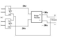
deepanger said:how connecting the 2 x 12v secondries make the ground?!
got confused in this
why cant i use the original wiring i sent 1st?
Because you are grounding the two centre taps which is not what you wish to do.
Look at UrSv's diagram (which wasn't posted when I started my last reply) which is also fine as the centre taps are not grounded.
This is another way of achieving what you want with only using one bridge, but personally, as bench power supplies are subject to a lot of abuse, and can sometimes fail, I would rather spend the small additional sum on the second bridge, and have two completely independent supplies.
This way, if one goes down the other is still OK, but it is simply a matter of choice.
Also, using two bridges, each one is loaded less this way, so it will be more robust.
Regards,
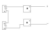
You need only ONE bridge rectifier.deepanger said:itried to draw the wiring but icouldnt get the bridge inputs
neither the ground!
can u complete it if u dont mind?
See UrSv diagram!
halo
deepanger said:itried to draw the wiring but icouldnt get the bridge inputs
neither the ground!
can u complete it if u dont mind?
Hi,
Much to my regret, I cannot as I cannot do anything other than text with my setup.
However, you are almost there.
Delete the connection betwen the two transformers joining the two secondaries together.
Draw a horizontal line from right to left across the centre of the diagram, halfway between the two transformers and the bridges, and this will be the 'O' volt or ground line.
Make another connection between the two bridges, from the - on the upper bridge, and the + on the lower one. where this line crosses the horizontal ground line, this is also an electrical connection ( the ground).
Add another horizontal line between the lower secondary of the upper TR to the upper bridge, and a similar line between the upper TR secondary and the lower bridge.
This the gives you two AC connections to each bridge, which is what you need and a single '0v' connection from each bridge to ground.
Also as you have shown, the upper bridge has a pos output and now a ground, and the lower bridge has a neg output and now a ground.
I cannot easily describe the orientation of the diodes within in each box representing the bridge, but unless someone else has beaten me to it (please!) I will look on the Forum for a suitable diagram to explain this.
Don't hesitate to come back until everything is absolutely clear as I would hate for you to get it wrong now.
Edit, I see in the meantime the comment that only one bridge is necessary, which agrees with my earlier comments, but as I also said, for a more robust bench PS the two bridge way is better.
Regards,
Hi Deepanger,
I see no one else has come up with a diagram as I suggested with two bridges yet, so I have just found the following on the Pass DIY site.
Have a look at : http://www.passdiy.com/images/projects/pearlfig4.gif
This uses two separate bridges, but only one single TR with two secondaries.
If you think of each of the outputs of your two TRs (when they have had their secondaries joined in series to give 24v, as I described before) in place of the two secondaries of the TR shown there (i.e. 30vac), you will have the same arrangement.
Just join the two closest (middle) outputs on that diagram to be grounded for the '0v' line.
This will give the most robust bench supply possible from such an arrangement, and for the cost of the extra bridge, I would go for that.
Otherwise, as I already said, the circuit proposed by UrSv is fine, if a little less versatile if you treat it harshly.
Please post again if you have any further queries.
Regards,
Hi subwo1,
Thanks a lot, that is exactly what I intended, and as you said, it does also have the additional advantage you mentioned.
For the cost of one extra bridge, it has to be worth it IMO.
It is incredibly frustrating when, like me, one cannot cope with any graphics, and "a picture is worth a thousand words."
Regards,
hi Bobken,
i am not very good with graphics either. i used microsoft paint to save and edit the diagram. That is why it is not neat.
Another advantage of using two bridges is that the ripple frequency is 120hz on each supply instead of 60hz. Then, you may be able to use smaller filter caps.
i am not very good with graphics either. i used microsoft paint to save and edit the diagram. That is why it is not neat.
Another advantage of using two bridges is that the ripple frequency is 120hz on each supply instead of 60hz. Then, you may be able to use smaller filter caps.
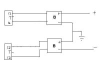
subwo1 said:hi,
This is what Bobken was getting at, i think. This way, you could always connect the two supplies in parallel if you want more current, also.
Really thanks all for the great replies am getting..
it really enlightened me alot!
one more ques. is if i wanna get more current handling , i should
connect 2 other additional transformers to the existing ones in
parellel ,right?
Hi,
Yes you can do what you suggest, Also, although you didn't specifically ask about it, you did mention having to wait to get hold of some higher current voltage regulators.
I don't know whether you are also aware of this, but current regs can be paralled too, to cope with higher current demands.
I am reluctant to say that *every* reg can be paralleled like this, but I know of no reason why not in theory, especially if they have inbuilt current limiting and thermal shut-down, both of which features are essential (very highly desirable, from the safety aspect, anyway!) IMHO, for your application.
It is always safer to look at manufacturers data sheets (available on the 'net, usually) for these parameters, as 'applications' advice is often given in this respect, and it may indicate whether paralleling is a good thing or not.
Otherwise, do what I did yesterday when I was looking for a suitable diagram to illustrate the dual transformer/bridge type power supply for you, and do a 'search' on the internet. I found hundreds of different suggested power supplies and arrangements, and it could be you will easily find the information you need from one of these.
Regards,
Bobken said:Hi,
Yes you can do what you suggest, Also, although you didn't specifically ask about it, you did mention having to wait to get hold of some higher current voltage regulators.
I don't know whether you are also aware of this, but current regs can be paralled too, to cope with higher current demands.
I am reluctant to say that *every* reg can be paralleled like this, but I know of no reason why not in theory, especially if they have inbuilt current limiting and thermal shut-down, both of which features are essential (very highly desirable, from the safety aspect, anyway!) IMHO, for your application.
It is always safer to look at manufacturers data sheets (available on the 'net, usually) for these parameters, as 'applications' advice is often given in this respect, and it may indicate whether paralleling is a good thing or not.
Otherwise, do what I did yesterday when I was looking for a suitable diagram to illustrate the dual transformer/bridge type power supply for you, and do a 'search' on the internet. I found hundreds of different suggested power supplies and arrangements, and it could be you will easily find the information you need from one of these.
Regards,
thanks man so much for ur efforts and help..
about obtaining more current with the lm3x7 igonna seek in this
and reread the datasheets again,
i already found an article that describes something called current
boosting with lm317 regulator using a power transistor, but it
requires about 36,000 or more filter capacitance!! ,, so ican find
it abit hard to implement..
so for now ill draw the design and post it in a new thread, and sure ill need ur gr8 experience in this...
thanks again,,
with regards.
DeepAnger.
- Status
- This old topic is closed. If you want to reopen this topic, contact a moderator using the "Report Post" button.
- Home
- Amplifiers
- Solid State
- Transformer problem