Hello.
I'm building/built an SC480, although i can't seem to set the queiscent current at all.
VR1 does have an effect, but not what i'm expecting.
The voltage across one of the setup resisitors (560ohm5W ones) is only ever maxed at 6v!.
This is a far cry lower than the 28v i need!.
Changing the resistor to max one way gets 6V max the other brings it down to numbers which are close to 0V.
I've compared the voltages at various points to the articles/jaycars ones, and i've found 3 that doint match up.
On the +40v side the two 100ohm resistors don't match.
The one in series with the 1N4148 diode, has a voltage of 0.445V (instead of 0.7V)
The 100ohm resistor which sits inbetween the +40V rail, and the E on Q6 has a voltage of 0.5v (instead of 0.9v).
The other mismatched voltage is the 6.8kohm 0.5w resistor in parrarel with a 12nF capacitor. I get a reading of 30V from this instead of 50.5V.
Anyone have any ideads?
Send them an email as they do respond with questions on their projects.
Check the voltages on your power supply first.
Most of these problems are components of the wrong value or in the wrong place. Check and recheck. Go away and have a smoke / coffee and check again. It's surprising how you can overlook these errors.
Check the voltages on your power supply first.
Most of these problems are components of the wrong value or in the wrong place. Check and recheck. Go away and have a smoke / coffee and check again. It's surprising how you can overlook these errors.
power supply is working fine.(checked and checked +39.9v and -39.9V on both rails  ) i think maybe a capacitor may not be working but?. i have my doubts about the 12nF cap thats in parrallel with the 6.8k resistor, cause im missing approx 20v along that resistor, so im wondering where it all went .
haha and i've been checking and checking again and checking my checking. if i've done it wrong im overlooking it badly , but i still could be, ill check again tonight lol.
i'll also mention that i had the power lines switched to begin with, though the 560ohm resistors were in place. I'd wager this was the problem, and some lil component has died, but it's my first amp, and i'm not to hot with the theory, so im not 100% sure what may have bit the dust.
So what would be most likely to kill itself, with about 2-3 seconds reverse polarity? . So i can start looking at things. Short of desoldering the whole kit, checking each component, and resoldering it again
i don't smoke matey, filthy filthy habit.
) i think maybe a capacitor may not be working but?. i have my doubts about the 12nF cap thats in parrallel with the 6.8k resistor, cause im missing approx 20v along that resistor, so im wondering where it all went .haha and i've been checking and checking again and checking my checking
. if i've done it wrong im overlooking it badly , but i still could be, ill check again tonight lol.i'll also mention that i had the power lines switched to begin with, though the 560ohm resistors were in place. I'd wager this was the problem, and some lil component has died, but it's my first amp, and i'm not to hot with the theory, so im not 100% sure what may have bit the dust.
So what would be most likely to kill itself, with about 2-3 seconds reverse polarity? . So i can start looking at things. Short of desoldering the whole kit, checking each component, and resoldering it again
i don't smoke matey, filthy filthy habit
.UPDATE: sorry for double postings, but i can't edit my posts .
I noticed that q13, and q11 were shorting onto the heatsink, continuity between the e leg and the heatsink.
This is still with the 560 ohm protection resistors in place.
Im not sure this was the cause at all but, just an unlucky coincidence. As when people have shorted transistors its meant to get really hot/blow fuses and resistors, which im getting the opposet effect of. Barely any current flow.
.I noticed that q13, and q11 were shorting onto the heatsink, continuity between the e leg and the heatsink.
This is still with the 560 ohm protection resistors in place.
Im not sure this was the cause at all but, just an unlucky coincidence. As when people have shorted transistors its meant to get really hot/blow fuses and resistors, which im getting the opposet effect of. Barely any current flow
.SC480 woes
Bojo2
Perhaps you should have mentioned the reversed polarity initially ? Failed semiconductor devices do not always become s/c,or smoke.
First find where the O/P device's emitter to heatsink s/c is coming from. Undo them, and then make sure that the s/c is gone.If then O.K., refit them with (preferably) new insulating bushes . Check again to make sure no s/c from emitters to heatsink. Replace all electros except bipolar.The PW5 resistors have hopefully saved the driver and O/P devices. The front end devices (hopefully) have been saved by circuit resistances limiting reversed current.To be on the safe side you should replace all BC639/BC640.
Hope this helps.
SandyK
Initially i did replace all those instances of transistors, but not much changed.
after that well i wasnt too sure were to go so i just bought another kit.
Set the queiscent well, did it at about 26.7V (kit wanted 28v).
Figured less voltage, less current, less heat, less stress kinda stuff. Less volume too but im not asking for heaps.
Anyway it worked fine for about 4 hours, then i heard a loud doof, and it was really quiet.
Thing was about a billion degrees!. im not sure what this would do, but the heatsink was thermonuclear kinda stuff.
Also the -40v fuse blew now. Would've that just been radiant heat? or something more dire?.
Im thinking i might need fans to cool this big boy down.
after that well i wasnt too sure were to go so i just bought another kit
.Set the queiscent well, did it at about 26.7V (kit wanted 28v).
Figured less voltage, less current, less heat, less stress kinda stuff. Less volume too but im not asking for heaps.
Anyway it worked fine for about 4 hours, then i heard a loud doof, and it was really quiet.
Thing was about a billion degrees!. im not sure what this would do, but the heatsink was thermonuclear kinda stuff
.Also the -40v fuse blew now. Would've that just been radiant heat? or something more dire?.
Im thinking i might need fans to cool this big boy down.
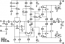
when setting the quiescent current i get these instructions.
"set vr1 fully anticlockwise and then apply power. With your multimeter set to read 50v or more, measure acroos one of the resistors and rotate vr1 clockwise until you get a reading of 28v. This gives a total quiescent current of 50mA...."
seems, q9 and q8 bit the dust in this too. Continuity between E and C. though now im worried all the fets on the heatsink went apart from q7.
anyone have ideas/ trouble shooting tips/ why the hell did this happen?.
"set vr1 fully anticlockwise and then apply power. With your multimeter set to read 50v or more, measure acroos one of the resistors and rotate vr1 clockwise until you get a reading of 28v. This gives a total quiescent current of 50mA...."
seems, q9 and q8 bit the dust in this too. Continuity between E and C. though now im worried all the fets on the heatsink went apart from q7.anyone have ideas/ trouble shooting tips/ why the hell did this happen?.
Oh man, endless trouble eh?
Care to post a hi-res pic of the amp, top + bottom?
For reference from now on though, if the heatsink gets too hot to touch (or even more than "fairly warm"), remove power IMO. It shouldn't get anywhere near that hot, especially not with the recommended heatsink (if that's what you've used).
Additionally, I know you're using it to run a sub, but for testing purposes run a cheap woofer with full-range input until its thoroughly tested - you're much more likely to hear if anything is going a bit wrong that way.
SC480
Richie
The link below may help. Good luck!
SandyK
http://img55.imageshack.us/my.php?image=sc480xr6.jpg
Richie
The link below may help. Good luck!
SandyK
http://img55.imageshack.us/my.php?image=sc480xr6.jpg
its funny, it seemed to have gone ages fine.
like it wasnt that hot when i was running it open on a chair for awhile. ( in case of smoke).
I even ran it full range on a speaker to see what it sounded like, (despite its problems it's the best sounding house amp i own).
Ohh hope the helps in solving the bias/quiscent current thing (they mean the same?) but the resistance im getting from the B leg of q7 to the E leg of q7 is 160ohms. That means VR1 would be set at 60 ohms i think.
Im gathering that maybe the quiescent current was set too high. Even though i set it to below what silicon chip said!. Thats really confusing me.
Ill post up some high res stuff later, have to dismantle the amp first XD, not sure what it will show on the top, all looks the same, but bottom may reveal something. ACK i hope its not bad soldering
like it wasnt that hot when i was running it open on a chair for awhile. ( in case of smoke).
I even ran it full range on a speaker to see what it sounded like, (despite its problems it's the best sounding house amp i own).
Ohh hope the helps in solving the bias/quiscent current thing (they mean the same?) but the resistance im getting from the B leg of q7 to the E leg of q7 is 160ohms. That means VR1 would be set at 60 ohms i think.
Im gathering that maybe the quiescent current was set too high. Even though i set it to below what silicon chip said!. Thats really confusing me
.Ill post up some high res stuff later, have to dismantle the amp first XD, not sure what it will show on the top, all looks the same, but bottom may reveal something. ACK i hope its not bad soldering
- Status
- This old topic is closed. If you want to reopen this topic, contact a moderator using the "Report Post" button.
- Home
- Amplifiers
- Solid State
- SC480 woes/ need smart people :D