To all,
Ok, I am opening up this subject again because... I found something very intetresting.
On the subject of not needing to connect the grid of a tube in order for it to work, I got some supporters, some who were tactfully saying I was right but wrong, or perhaps just plain old full of it, and one who adamantly said I was an ignoramus, and knew little about anything tubes and electronics.
OK, I recently had the pleasure of building/repairing/modifying two amplifiers from two separate modern kit and amp manufacturers/competitors, Bottlehead and Sun Audio.
Now, I am not promoting or denegrating their products. They are both very good. They are both 2A3 single ended.
They are both direct coupled inputs! That is, the connection from the RCA jack to the tube is a straight wire. The amps worked very well when my CD player was directly connected... pure AC coupled! No DC connection to the cathode except that which anyone who really knows tube technology would tell you, the internal connection.
SO, I guess Doc Bottlehead and the engineers at Sun Audio are also ignoramuses.
Gabe
I don't know if those guys are ignorami or not, never having heard of these companies, but if there's no provision for some sort of grid-leak resistance, it's a design which is inherently unreliable (not the first time that latter-day tube "designers" have paid no attention to the lessons of the past). My guess is that, despite the ac coupling of your CD player, there's an output resistor to ground following the output cap- otherwise, the player would have horrible turn-on and turn-off bangs. And that resistor is acting as a remote grid leak.
Direct wire connection to the grid, even with a grid-leak resistor to ground, is poor design practice anyway, an invitation to RFI and oscillation. But I've seen highly regarded (not by me) amps selling for 5 figures that had horrific slewing distortion, blew up output tubes on a regular basis, and had power bandwidths orders of magnitude below spec. I guess that's what their "designers" called "musical." So merely making an amp vulnerable to external noise is not the worst error a "designer" can commit.
Direct wire connection to the grid, even with a grid-leak resistor to ground, is poor design practice anyway, an invitation to RFI and oscillation. But I've seen highly regarded (not by me) amps selling for 5 figures that had horrific slewing distortion, blew up output tubes on a regular basis, and had power bandwidths orders of magnitude below spec. I guess that's what their "designers" called "musical." So merely making an amp vulnerable to external noise is not the worst error a "designer" can commit.
Ok....so....let's go back to the top and tell me exactly WTF we're talking about here? 
If you mean no DC resistance to the grid, I've done a little experimentation with that. Not much, mind you.
The jist of it is, the tube will self-bias at a few volts below cathode. But, if the tube's been working hard, it's possible that grid emission may take over and it climbs positive! This makes for a runaway situation, of course.
Tim
SY,
Right, I agree. All my amps have grid resistors.
My contention, though, was that it was not necessary to have it for the tube to work. And if you recall, in my argument I did say the amp would be unstable (I guess that is what is considered "musical", since many also desire the 5Y3 rectifier, a tube that changes the B+ by merely looking at it).
BTW, those amps sound very good, FWIW. Also, there are quite a few other "engineers", if you like, who also design their amps with no input grid resistor or coupling cap.
As for the CD player... I will look in it physically. It does have a mute to disconnect output when not playing. But I am pretty sure there is no resistor after the cap. I mean, why put one there if the next stage is usually a preamp with an input resistor or a stepped attenuator anyway (think "bean counters")?
At any rate, this prompted me to use a coupling cap after the preamp I was using, since its output was designed to mate with a power amp that had a coupling cap in it, so there was none in the output. So it was changing the input tube's bias in the power amp. I isolated it with caps.
Sun Audio is not cheap. They are a Japanese company, if that means anything. They use Tamura iron.
Bottlehead is home of the Audio Asylum forum. They tout Magnequest iron.
Gabe
SY said:2.5 watts at 5% distortion for $1200. Barnum was right.
This is all you need to know about an amp to judge its sonic merits? You're good, really good!

LOOK MA,NO GRID LEAKS...
Hi,
Yes...it will work.
If I read you correctly the input valve on the amps you worked on had no gridleak resistors and had cathode bias.
The tube will still bias itself through its' internal capacitance form grid to cathode,no problem there.
But in real life as soon as you connect a CDP or preamp to that it will effectively see the bleeder R at the output of these devices.
This may be anything from a few K to a M ohm.
So your gridleak will be that resistor and will always vary anyway you look at it.
Imagine the manufacturers would have used a 100K gridleak R and you hook up a CDP with a 10K bleed R at the output.
Mow you will have two resistors in // and the end value is going to be smaller than the 10 K,right?
Naturally,if you have another fool at the other end of the stick following the same reasoning and he doesn't use any bleeder at the output of his gear you're going to be in for a few surprises too.
The way I see it: it will work alright,another costfactor is reduced,but it sure is not good practice not to terminate the transmission lines and leave it to the inherently nonlinearity of the tube to determine this.
Cheers,
Hi,
My contention, though, was that it was not necessary to have it for the tube to work.
Yes...it will work.
If I read you correctly the input valve on the amps you worked on had no gridleak resistors and had cathode bias.
The tube will still bias itself through its' internal capacitance form grid to cathode,no problem there.
But in real life as soon as you connect a CDP or preamp to that it will effectively see the bleeder R at the output of these devices.
This may be anything from a few K to a M ohm.
So your gridleak will be that resistor and will always vary anyway you look at it.
Imagine the manufacturers would have used a 100K gridleak R and you hook up a CDP with a 10K bleed R at the output.
Mow you will have two resistors in // and the end value is going to be smaller than the 10 K,right?
Naturally,if you have another fool at the other end of the stick following the same reasoning and he doesn't use any bleeder at the output of his gear you're going to be in for a few surprises too.
The way I see it: it will work alright,another costfactor is reduced,but it sure is not good practice not to terminate the transmission lines and leave it to the inherently nonlinearity of the tube to determine this.
Cheers,
jeff mai said:
This is all you need to know about an amp to judge its sonic merits? You're good, really good!
Not all, but enough. I don't buy homeopathic drugs, wear magnetic insoles, or have my auras read, either.
He he...me neither..I don't buy homeopathic drugs, wear magnetic insoles, or have my auras read, either.
I don't believe in luck either. There's no such thing! It's a method of diverting blame.
I told this to a colleague who was a bit depressed due to his "bad luck". Unfortunately I never saw him again, because he died sitting in his car in the carpark.
Life's odd, but not irrational.
And, UFO's are "unidentified"
Otherwise they're something else!Cheers,
SY said:there's an output resistor to ground following the output cap- otherwise, the player would have horrible turn-on and turn-off bangs. And that resistor is acting as a remote grid leak.
Exactly. I think "Doc Bottlehead" (WTF???) is taking a big risk in hoping that all the units you hook this thing up to will have a resistance to ground.
Gabe, I can't believe you're dredging this up again?!!?
You keep confusing two issues - developing signal voltage, and providing a dc path between the grid and cathode. In your example, there is a path in there somewhere, or the tube will not function.
RAGS ALL OVER.
Hi,
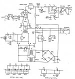
It's your typical grounded grid circuit and as such has no bearing on what Gabe put forward.
Joel,
Actually it's the European Union jack.
The Belgian tricolours are like the German one (our first king was German) but the stripes are vertically aligned iso horizontally.
Cheers,
Hi,
Looks like an ARRL schematic, I'd guess a 60s or 70s Handbook, not 50s since the SS diodes...
It's your typical grounded grid circuit and as such has no bearing on what Gabe put forward.
Joel,
Frank, is that really the flag of Belgium? I like it! Very understated.
Actually it's the European Union jack.
The Belgian tricolours are like the German one (our first king was German) but the stripes are vertically aligned iso horizontally.
Cheers,
Gabe, I can't believe you're dredging this up again?!!?
You keep confusing two issues - developing signal voltage, and providing a dc path between the grid and cathode. In your example, there is a path in there somewhere, or the tube will not function.
BTW, WTF means "What The F$#%." Oh, BTW means "By The Way."
I only "dredged it up again" because I found a couple of examples to prove my point. Your contention was a path was necessary from the grid to cathode. If you said "internally", I would have agreed and that would have been the end of it. Theories and statements in electronics should require solid proof. So here I have presented this proof.
I am not confusing anything.
Do you know what you get when you put a positive voltage on the anode and a negative voltage on the cathode of a triode with nothing on the grid? A diode. The tube will conduct! The grid is there to control that initial flow of current. All that is really needed is a negative voltage with relation to the cathode in order to control the flow. That control can come from a pure AC source. I repeat myself here, that is not a practical practice, to be sure. But the tube will work. It will flow current. It will transfer the change in grid voltage. It needs a static grid to cathode voltage to bias it at idle. That can come from the cathode alone. There are some tubes whose specs allow them to work still in class A with a grid bias of zero.
I am sorry to sound condescending here, or patronizing, but it seems that with all your "book knowledge" you have missed something.
But, these two amp examples, of many I have come across, show that the tube will work without an external path.
If it is a problem for you to read things that are repeated, just ignore it. That is going to happen alot, since this is a subject with a finite number of subsets.
If you have a problem with me, just click on my profile and choose the "ignore" option below. Then anything I post you won't be informed of or be aware of.
But, you certainly don't dictate here or anywhere else in this country what whomever says. So... unless you like to have your freedoms revoked, get off my case! Because your freedom of speech stops with your trying to supress mine.
And if what I have posted here is wrong in any way, I would hope that the moderator would be the one to tell me so, not you.
Gabe
Gabe, first you really need to calm down!
Second, this isn't some first amendment issue, and I certainly don't have a vendetta against you.
I expressed some.... frustration. I apologize. But I thought we had already covered this ad nauseum. However, I see there is still some confusion. Your "proof" is actually not proof of anything other than doc bottlehead's lack of a grid resistor!
As for your other points:
A triode is not a diode. I do not want, or ask it to behave like a diode. For a triode to "work" (ie. perform the functions of a triode) the grid needs a dc path back to the cathode. And no, this is not "internal" in any tube I've ever seen.
I'll happily repeat again, and I would welcome somebody trying to disprove it, but:
ALL THE ELECTRODES IN ANY TUBE MUST HAVE A DC PATH TO THE CATHODE.
Cheer up!
Joel
Second, this isn't some first amendment issue, and I certainly don't have a vendetta against you.
I expressed some.... frustration. I apologize.
But I thought we had already covered this ad nauseum. However, I see there is still some confusion. Your "proof" is actually not proof of anything other than doc bottlehead's lack of a grid resistor! As for your other points:
A triode is not a diode. I do not want, or ask it to behave like a diode. For a triode to "work" (ie. perform the functions of a triode) the grid needs a dc path back to the cathode. And no, this is not "internal" in any tube I've ever seen.
I'll happily repeat again, and I would welcome somebody trying to disprove it, but:
ALL THE ELECTRODES IN ANY TUBE MUST HAVE A DC PATH TO THE CATHODE.
Cheer up!
Joel
- Status
- This old topic is closed. If you want to reopen this topic, contact a moderator using the "Report Post" button.
- Home
- Amplifiers
- Tubes / Valves
- No grid connection