I am very much interested in the ACE-bass principle, invented by K.E. Stahl back in the seventies. I’ve found the patent of the principle and did a lot of searching on the internet. In this tread on DIYAUDIO I found a circuit of a prototype of Bjorno’s ACE-bass amp design.
I am planning to build such a thing to experiment with, and maybe when it give satisfying results build a sub for daily use.
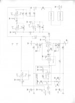
Bjorno mentioned in one of his posts of the tread that the amp part can be replaced by an “gainclone” amp. This would be very practical since I’ve already built a Gainclone amp, which I can use for this project.
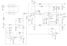
I have redrawn Bjorno’s circuit diagram with a Gainclone amp instead of the original amp. My question is: will this work, or am I forgetting some critical things here?
Bjorno, what does P4 (100k) do at the + input of uA748 do? Offset or something?
I am hoping that any of you can give me some feedback on this design.
Thanks,
Durxter
I am planning to build such a thing to experiment with, and maybe when it give satisfying results build a sub for daily use.
Bjorno mentioned in one of his posts of the tread that the amp part can be replaced by an “gainclone” amp. This would be very practical since I’ve already built a Gainclone amp, which I can use for this project.
I have redrawn Bjorno’s circuit diagram with a Gainclone amp instead of the original amp. My question is: will this work, or am I forgetting some critical things here?
Bjorno, what does P4 (100k) do at the + input of uA748 do? Offset or something?
I am hoping that any of you can give me some feedback on this design.
Thanks,
Durxter
Attachments
Bjorno, what does P4 (100k) do at the + input of uA748 do? Offset or something?...
durxter,
Thank you for re-writing my old schematic , it looks good as far as I can see. I’ve tested with a 3886 amp and it worked well.
Tip;You should insert a 10 K Ohm pot P (Rrs) in series with the Rrs resistor to trim the negative output resistance starting at max pot R value, then vary between this pot and pot P4, i.e. for every setting of P (Rrs) the output will drift and has to be counteracted with P4.
If you also have a PSpice program available then it’s very easy to model any driver in a closed box with a fixed Qtc and alter the virtual T/S parameters to target a new more suitable and preferred value of the Qtc at another chosen corner frequency.
b
Bjorno,
Thanks for the quick reaction to my post!
I didn't put those values in my circuit because they have to be calculated to get the parameters you want. But I don't understand how to determine the Amplification Constant (G) to get Rg. I hope you can explain that to me.
Another question about the ACE bass principle in common:
What is the advantage when using ACE-bass with a sealed box over a Linkwitz Transform Circuit? In a Dutch Elektor book about speaker design, the author mentions that for closed cabinets the ACE principle has no advantages over LT. I hear different stories about that. I thought that one of the advantages of ACE bass is that you don’t need much extra power to go low, as with LT ( or ELF).
For the first tests I plan to use standard 7inch Focal woofers (in sealed enclosure), they don’t have an extreme X-max and a max power of only 60 Watts. I hope this works out.
Durxter
Thanks for the quick reaction to my post!
R14 = 22k Ohm, seed value for Ra = 330k Ohm, R19 = 68 k Ohm, seed value for Rrp = 150k Ohm, seed value for Rlp = 68k Ohm, seed value for Ccp = 47nF, seed value for Ci = 0.22 uF.
I didn't put those values in my circuit because they have to be calculated to get the parameters you want. But I don't understand how to determine the Amplification Constant (G) to get Rg. I hope you can explain that to me.
Another question about the ACE bass principle in common:
What is the advantage when using ACE-bass with a sealed box over a Linkwitz Transform Circuit? In a Dutch Elektor book about speaker design, the author mentions that for closed cabinets the ACE principle has no advantages over LT. I hear different stories about that. I thought that one of the advantages of ACE bass is that you don’t need much extra power to go low, as with LT ( or ELF).
For the first tests I plan to use standard 7inch Focal woofers (in sealed enclosure), they don’t have an extreme X-max and a max power of only 60 Watts. I hope this works out.
Durxter
Tip;You should insert a 10 K Ohm pot P (Rrs) in series with the Rrs resistor to trim the negative output resistance starting at max pot R value, then vary between this pot and pot P4, i.e. for every setting of P (Rrs) the output will drift and has to be counteracted with P4.
Or use a first order highpass with low cutoff-frequency at the input of the power amp (like Stahl's patent suggests !). It worked well for me with a 2Hz cutoff.
Regards
Charles
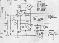
Here is my effort. It only does negative resistance Qe whereas the ACE
tweaks the Compliance (VAS) and the moving mass
Will give much better results than a sealed box with LT in terms of cone excursion, voice coil heating and depth of bass from a given size box.
R26 should goto the junction of C16 and r15 to avoid DC offset problems.
tweaks the Compliance (VAS) and the moving mass
Will give much better results than a sealed box with LT in terms of cone excursion, voice coil heating and depth of bass from a given size box.
R26 should goto the junction of C16 and r15 to avoid DC offset problems.
Attachments
..But I don't understand how to determine the Amplification Constant (G) to get Rg.
The global gain G relies of the open loop gain through the band pass filter (closed through the gyrator feedback) x the closed loop of the power amplifier = Ao being much larger than G.
As G is 1/R14 x (R18xR26)/(R46xR25) you can think of Ao as an inverting amplifier (in reality positive gain) with the input series resistor = R14 and the feedback resistor =(R18xR26)/(R46xR25).
What is the advantage when using ACE-bass with a sealed box over a Linkwitz Transform Circuit?
I have never compared with LT and in a sealed box, I used my amplifier for small volume ported boxes (large ports) only and my favourite driver is the low inductance SS 21W85550.
The power transistors runs very cool as the energy transfer from the amplifier to the speaker has no troublesome VSWR at all, compared to the opposite when using LT at higher gain losses.
Or use a first order highpass with low cutoff-frequency at the input of the power amp (like Stahl's patent suggests !). It worked well for me with a 2Hz cutoff.
Thank you Charles for this reminder, it would be very easy to incorporate this safety approach if a first order HP pole is placed at or below 2 Hz.
At time when I worked with the my amplifier I tested with 2 series 100 uF capacitors and 1N4148 diodes for the leak currents, connected bipolar at the inputs of R16 and R28 but later when I made circuit boards I eliminated these bulky capacitors with the offset pot.
b
I have never compared with LT and in a sealed box, I used my amplifier for small volume ported boxes (large ports) only and my favourite driver is the low inductance SS 21W85550.
The real advantage IMO is indeed only when this circuit is used with a ported box. The interaction between drivers and box is as if the drivers actually had the simulated parameters - something that wouldn't happen if the "un - ACEd" driver(s) were used with the same box and tuning. But it can't change the laws of physics and so the efficiciency remains low at low frequencies. But it is able to take advantage of the reflex loading, especially in terms of driver displacement.
I assume that it has about nil advantage over an LTF in a closed box.
Regards
Charles
So actually ACE bass might not be worth the effort when using it with a sealed enclosure? Wouldn't it be easier then to use the patent of Yamaha (only negative resistance), since you will not get the simulated parameters when using ACE with a sealed box.
Do you have experience with that circuit?
Thanks
Do you have experience with that circuit?
Thanks
The desirable properties of a driver for a small vented box are low Vas (stiff compliance) low Fs and low Qts. The ACE is used to achieve these parameters. With a sealed box the matching of parameters is not so difficult and the response can simply be flattened with a LT. However when you look at the excursion its much lower with a vented box,
especially with a high pass filter making a sixth order design.
I do not think there is any advantage in using a complex ACE amplifier with a sealed box. Interesting idea though!
especially with a high pass filter making a sixth order design.
I do not think there is any advantage in using a complex ACE amplifier with a sealed box. Interesting idea though!
FYI:
Basta! in my signature can simulate the effects of ACE-bass. The circuits you have posted results in an output impedance with a LCR circuit and a negative resistance. These component values can be entered in Basta! and their effects on frequency response are simulated.
Basta! in my signature can simulate the effects of ACE-bass. The circuits you have posted results in an output impedance with a LCR circuit and a negative resistance. These component values can be entered in Basta! and their effects on frequency response are simulated.
Thanks all for your help so far.
I tried to do some simulations with WinISD for both sealed and reflex cabinet.
Parameters of Focal speaker without ACE:
Sd : 0,0165 m2
fs : 40,4 Hz
Vas : 37,2 l
Qts 0,294
Mmd : 0,0161 kg
Bl : 6,05 N/A
Rdc: 3 Ohm
Cms*: 0,0009639 m/N (*calculated)
Qes* : 0,34
Qms* : 2,404
Rms* = 1,7 kg/s
Simulated parameters for sealed enclosure of 20l with Qtc = 0,5 :
fs : 11,76 Hz
Mmd : 190 g
Rms : 35,55
Qes : 1,151
Qms : 0,395
This gives a -3db point of 30 Hz. The only thing that worries me is that WinISD gives a SPL of less than 70db. Can this be true, or is it different in real life because the added mass to the cone is only virtual.
I also tried to simulate a bassreflex enclosure . The problem is that enclosures smaller than 20l needs port length of several meters! to get a low fs (30Hz or lower). The only way to get a normal length is to increase Vas, but thats not what you want! Simulated parameters:
fs : 19,6 Hz
Mmd : 68,4 g
Rms : 16.45
Qes : 0.690
Qms : 0,512
How can I determine the Qts and Vas for the desired results?
I hope that someone here can give me some help with the design process.
durxter said:Thanks all for your help so far.
I tried to do some simulations with WinISD for both sealed and reflex cabinet.
Parameters of Focal speaker without ACE:
Sd : 0,0165 m2
fs : 40,4 Hz
Vas : 37,2 l
Qts 0,294
Mmd : 0,0161 kg
Bl : 6,05 N/A
Rdc: 3 Ohm
Cms*: 0,0009639 m/N (*calculated)
Qes* : 0,34
Qms* : 2,404
Rms* = 1,7 kg/s
Simulated parameters for sealed enclosure of 20l with Qtc = 0,5 :
fs : 11,76 Hz
Mmd : 190 g
Rms : 35,55
Qes : 1,151
Qms : 0,395
This gives a -3db point of 30 Hz. The only thing that worries me is that WinISD gives a SPL of less than 70db. Can this be true, or is it different in real life because the added mass to the cone is only virtual.
How can I determine the Qts and Vas for the desired results?
I hope that someone here can give me some help with the design process.
Cms=1/((2*pi*fs)²*Mms)=0.96 mm/N
Vas=Cms*rho0*c²*Sd²=37 litres
Qts=1/(1/Qes+1/Qms)=0.29
The sensitivity for the driver is the same as it would be in the box in question without ACE. The simulator you used, that knows nothing about ACE, calculates the sensitivity of an imaginary driver with the desired parameters.
A simulation of the closed box becomes like this. Thin lines are the driving voltage from the amplifier. Note the resonance peak that occurs at ~300Hz; this is typical for ACE designs, and kan be taken care of, for example by adding a conjugate link.
An externally hosted image should be here but it was not working when we last tested it.
Svante,
Thanks for the reply and the simulation in Basta.
The parameters you calculated here:
Cms=1/((2*pi*fs)²*Mms)=0.96 mm/N
Vas=Cms*rho0*c²*Sd²=37 litres
Qts=1/(1/Qes+1/Qms)=0.29
are actually the original driver parameters. For the sealed enclosure I only added imaginary mass and changed Rms to get the same Qts as before. The resonance peak won't be a problem when I use a lowpass at +- 80Hz right?
My question about Vas and Qts was for a basreflex enclosure. Which values of Vas and Qts (by changing Cms) should I choose for optimal results in a basreflex enclosure, without the need of ports of a few meters. Or is it just impossibe?
I wish to compare sealed and basreflex to make a decision what principle I will use, but the basreflex simulations doesn't give usable results.
Hope you can help...
durxter said:Svante,
Thanks for the reply and the simulation in Basta.
The parameters you calculated here:
Cms=1/((2*pi*fs)²*Mms)=0.96 mm/N
Vas=Cms*rho0*c²*Sd²=37 litres
Qts=1/(1/Qes+1/Qms)=0.29
are actually the original driver parameters. For the sealed enclosure I only added imaginary mass and changed Rms to get the same Qts as before. The resonance peak won't be a problem when I use a lowpass at +- 80Hz right?
My question about Vas and Qts was for a basreflex enclosure. Which values of Vas and Qts (by changing Cms) should I choose for optimal results in a basreflex enclosure, without the need of ports of a few meters. Or is it just impossibe?
I wish to compare sealed and basreflex to make a decision what principle I will use, but the basreflex simulations doesn't give usable results.
Hope you can help...
The lowpass @ 80 Hz has some extra demands on steepness due to the peak. I mean, it is after all a lift of some 5 dB in my simulation (which relied on guesswork regarding Le) and the filter would then have to attenuate s much at 300 Hz so that the 5 dB extra does not matter.
Ah... Ok so "optimal" choice of driver parameters varies depending on who you ask.
") One way to go is to make a butterworth alignment, which would require Qts=0.38, fs=fh, Vb=Vas/1.4 if the box and vent are lossless. OTOH a butterworth alignment does not consider the bass lift that the typical room shows, so it might be wise to tune the box bit lower than fh=fs.
One way to go is to make a butterworth alignment, which would require Qts=0.38, fs=fh, Vb=Vas/1.4 if the box and vent are lossless. OTOH a butterworth alignment does not consider the bass lift that the typical room shows, so it might be wise to tune the box bit lower than fh=fs.Long vents is the inevitable result of low tuning, small boxes and high output levels. This is the most severe limitation of ACE IMO. There are at least two ways around it, one is to surrender and use a closed box, the other is to use a passive radiator.
After reading all this I will go for a bassreflex enclosure. I will be using a 10" Seas driver type:
CA25RE4in a 47 liter enclosure with a port of 35cm dia.:4,7 cm. This will give me a -3db of 25 Hz (SBB4 allignment). 4,7 cm may be a little small, but it's the only way to fit it into the enclosure without bends. The max air speed will be below 17m/s at low freq. at Xmax.
Driver Le is 1,6 mH, wich effect would this have on the higher freq. response?
I used this parameters for calculations:
New driver parameters:
M'ms = 156,5 g
C'ms = 0,57 mm/N
R'ms = 34,4 kg/s
Vas = 100l
Q'ms = 0,48
Q'es = 1,06
Q'ts = 0,33
This gives:
Cp = 1,33mF
Rp = 2,75 Ohm
Lp = 98 mH
G= ????
I still don't understand how to determine G (Rg)
Does this mean that Ao (gain of poweramp 19x in my case?) is the same as G. Since the formula of A of an inverting amp is the same as formula for G.
A = Feedback R / Series R
= ((R18*R26)/(R24*R25) / R14)
It's maybe very simple for you, but it's just not clear to me.
I hope you can help.....
CA25RE4in a 47 liter enclosure with a port of 35cm dia.:4,7 cm. This will give me a -3db of 25 Hz (SBB4 allignment). 4,7 cm may be a little small, but it's the only way to fit it into the enclosure without bends. The max air speed will be below 17m/s at low freq. at Xmax.
Driver Le is 1,6 mH, wich effect would this have on the higher freq. response?
I used this parameters for calculations:
New driver parameters:
M'ms = 156,5 g
C'ms = 0,57 mm/N
R'ms = 34,4 kg/s
Vas = 100l
Q'ms = 0,48
Q'es = 1,06
Q'ts = 0,33
This gives:
Cp = 1,33mF
Rp = 2,75 Ohm
Lp = 98 mH
G= ????
I still don't understand how to determine G (Rg)
As G is 1/R14 x (R18xR26)/(R46xR25) you can think of Ao as an inverting amplifier (in reality positive gain) with the input series resistor = R14 and the feedback resistor =(R18xR26)/(R46xR25).
Does this mean that Ao (gain of poweramp 19x in my case?) is the same as G. Since the formula of A of an inverting amp is the same as formula for G.
A = Feedback R / Series R
= ((R18*R26)/(R24*R25) / R14)
It's maybe very simple for you, but it's just not clear to me.
I hope you can help.....
durxter said:After reading all this I will go for a bassreflex enclosure. I will be using a 10" Seas driver type:
CA25RE4in a 47 liter enclosure with a port of 35cm dia.:4,7 cm. This will give me a -3db of 25 Hz (SBB4 allignment). 4,7 cm may be a little small, but it's the only way to fit it into the enclosure without bends. The max air speed will be below 17m/s at low freq. at Xmax.
Driver Le is 1,6 mH, wich effect would this have on the higher freq. response?
I used this parameters for calculations:
New driver parameters:
M'ms = 156,5 g
C'ms = 0,57 mm/N
R'ms = 34,4 kg/s
Vas = 100l
Q'ms = 0,48
Q'es = 1,06
Q'ts = 0,33
This gives:
Cp = 1,33mF
Rp = 2,75 Ohm
Lp = 98 mH
G= ????
I still don't understand how to determine G (Rg)
Does this mean that Ao (gain of poweramp 19x in my case?) is the same as G. Since the formula of A of an inverting amp is the same as formula for G.
A = Feedback R / Series R
= ((R18*R26)/(R24*R25) / R14)
It's maybe very simple for you, but it's just not clear to me.
I hope you can help.....
Hmm...
Unless I am doing something wrong here, your design suggestion seems to be wrong. Your virtual driver parameters suggest a fs' of 16.8 Hz (1/(2*pi*sqrt(0.57e-3*0.1565))=16.8), yet the vent and box dimensions suggest a tuning to ~38 Hz. Using the virtual driver parameters (fs'=16´.8 Hz, Vas'=100 liter, Qts'=0,33 box 47 liter tuned to 38.4 Hz, I get the green curve. An actual ACE implementation with Le and Le loss of the SEAS driver results in the blue curve (without conjugate link).
My suggestion is to aim at fs'=20, Vas'=100, Qts'=0.3 and a conjugate link of 5.8 ohm, 47 µF (red curve).
A butterworth solution is also possible, with fs'=20, Vas'=70, Qts'=0.383 (yellow curve). Same conjugate link is used in the simulation.
An externally hosted image should be here but it was not working when we last tested it.
The Rg is just a resistor controlling gain, like a volume control.
I would like to recommend you to get Basta!. I usually don't want to make such recommendations here in the forum since it can be interpreted as advertising, but I actually don't know of any other software that simulates ACE. I think you would be helped by simulating this yourself so I hope it is Ok. It is rather cheap. There is a link in my signature.
Svante,
Strange things happening here. I've been doing some simulations with WinISD and a spreadsheet from www.diysubwoofers.org they both say that the design I made should be right....
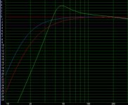
In the response graph below you see:
- Blue line: Fs 16,8 Hz
Qts 0,33
Vb 47 ltr
Portlength 35 cm, dia 4,7 cm
- Red line: Fs 20Hz
Qts 0,33
Vb 38,7 ltr
Port length 30cm, dia 4,7cm
- Green line: Fs 16,8 Hz
Qts 0,33
Vb 47 ltr
Portlength 35 cm, dia 10 cm
The only reason I can think of is that you didn't choose the same portdiameter (4,7 cm) as I did. When taking 10 cm I get the same response as in your graph with -3db of around 35Hz and a large peak. What pipe dimensions and enclosure volume did you use for the simulation?
I think I will go for your suggestion (red line). It looks better than my suggestion. I thought that a lower tuning gives better group delay, am I right?
About Basta;
I see that you can only pay by creditcard, which I don't have...are there other options?
But most of the changed parameters can be simulated with for example WinISD, except for the effect of Le, right?. Very nice software though.
Strange things happening here. I've been doing some simulations with WinISD and a spreadsheet from www.diysubwoofers.org they both say that the design I made should be right....
In the response graph below you see:
- Blue line: Fs 16,8 Hz
Qts 0,33
Vb 47 ltr
Portlength 35 cm, dia 4,7 cm
- Red line: Fs 20Hz
Qts 0,33
Vb 38,7 ltr
Port length 30cm, dia 4,7cm
- Green line: Fs 16,8 Hz
Qts 0,33
Vb 47 ltr
Portlength 35 cm, dia 10 cm
The only reason I can think of is that you didn't choose the same portdiameter (4,7 cm) as I did. When taking 10 cm I get the same response as in your graph with -3db of around 35Hz and a large peak. What pipe dimensions and enclosure volume did you use for the simulation?
I think I will go for your suggestion (red line). It looks better than my suggestion. I thought that a lower tuning gives better group delay, am I right?
About Basta;
I see that you can only pay by creditcard, which I don't have...are there other options?
But most of the changed parameters can be simulated with for example WinISD, except for the effect of Le, right?. Very nice software though.
Attachments
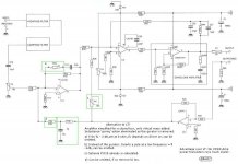
Here is my circuit, with the changed DC blocking with a 2Hz highpass filter, like charles suggests;
Is this how it should be done?
What value should I choose for the Bias resistor R30 in this new situation?
Or use a first order highpass with low cutoff-frequency at the input of the power amp
Is this how it should be done?
What value should I choose for the Bias resistor R30 in this new situation?
Attachments
- Home
- Loudspeakers
- Subwoofers
- ACE-bass amplifier design