carver pm 1.5 capasitor replacement
hi all!
i have a carver PM 1.5 amplifier with i suspect a dead voltage Regulator however i noticed that 4 of the large caps are bulged and dried up, according to the schematics however the four in question were originally two 2200micro 50/80v dual core capacitors which are no longer available. they have already been replaced with 4 separate caps wired up like the dual ones. but the thing is replacement radial electrolytics are about 20mm diameter max but the current ones are huge are the smaller ones correct or are there some specialist caps i should be using?
thanks
tim
Newer electrolytic caps are generally much smaller than those of even 10 years ago.
A new Nichicon HE 2200µf 50V electrolytic can take almost 3.7A of ripple current, and a new Nichicon VR 2200µf 100V cap can take 2.4A of ripple.
Define 'huge'.but the current ones are huge
A new Nichicon HE 2200µf 50V electrolytic can take almost 3.7A of ripple current, and a new Nichicon VR 2200µf 100V cap can take 2.4A of ripple.
PM 1.5
Hi jifop, capacitor failure is not an uncommon thing in 1.5 under extreme usage and time, but check for AC leakage you could have a bad diode in the low or mid voltage supply rails, or something could be a little off in the voltage tracking circuit for the triac or even some shorted windings in the field coil.
The two large 130VDC capacitors should also show signs of distress if a coil or voltage tracking problem is underfoot, the voltage tracking is taken of the high voltage rails.
As for replaceing the dual voltage caps due to modern size reductions it is easy to etch a small PC board and use separate low and mid voltage caps with better rateings then the originals in the same space.
Check for other problems there could be something more serious underway.
If your are unfamiliar with the inner workings of a Carver amp I would suggest sending it to a qualified service person that has working knowledge of Carvers.
Good luck.
PM 1.5
Oh by the way , do you mean a bad triac or a 2n3055 2n2995 that are mounted on the back wall of the amp next to the inputs?? the two transistors are a descrete regulator designed to deliver +/- 15VDC to the meters and protection circuit.
I ask because triac faults are uncommon and most likley are signs of more serious problems or poor service work.
urm, sorry last post made no sense, there is a resistor burning out on one of the legs of the voltage regulator, i thought the reg may be dead?
it was then that i noticed the caps but could the dead caps cause problems?
carvers are a new beast to me in all honesty, the two large capasitors look fine externally. i am happy to work through it i have all the tools and i wouldn't know where to start with finding a carver repair agent.
it was then that i noticed the caps but could the dead caps cause problems?
carvers are a new beast to me in all honesty, the two large capasitors look fine externally. i am happy to work through it i have all the tools and i wouldn't know where to start with finding a carver repair agent.
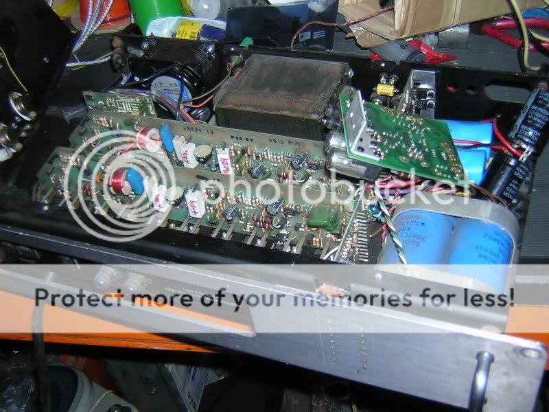
right here we go, this is the amp as i got it, obviously it has had a new fan fitted and the cap mod done. all i have done to it is turn it on and bell out the diodes.
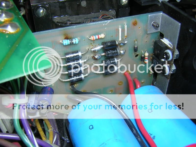
as i said when powered up R67 smokes like a goodun, i assumed this to be something related to the regulator, could that be caused by the caps?
anyway here are the pictures
Overall photo
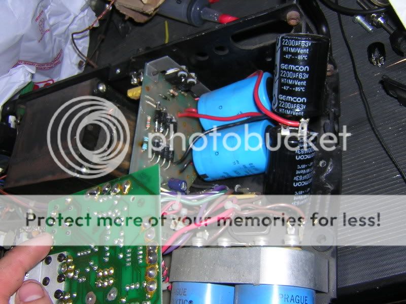
Caps
Burnt resistor
So what should i do? where should i start? and what capasitors should i be buying? rs is my supplier of coice if possible
as i said when powered up R67 smokes like a goodun, i assumed this to be something related to the regulator, could that be caused by the caps?
anyway here are the pictures
Overall photo
Caps
Burnt resistor
So what should i do? where should i start? and what capasitors should i be buying? rs is my supplier of coice if possible
PM 1.5
Where to start? first does the amp power on if so does it go into protection, thats is if you have tried if not dont.
As for the caps, there used to be a guy on Ebay that sold a upgrade PC board and caps thats a direct solder in, but I cant for the life of me remember his ID. You can use any reasonable replacements Ive used 4700uf 50VDC for the low volt and 4700uf 75VDC for the mid volt both smaller size from nichon but any decent cap with the proper rateings will do.
Check the power supply diodes looks like somebody hacked them.
If I had to hazzard a guese somebody connected the low volt and mid volt AC from the field coil backward check the color codeing of the wires against the schematic I think the reds low orange mid and yellow high.
Then check the two transistors on mounted on the back wall the 2n3055 and 2995 they are a voltage regulation circuit and replace any bad related parts i.e. resistors diodes. the burnt resistor I believe is a 15ohm current limiter and should have a mate on the other power leg.
Then check for any shorted windings on the coil, also check the triac that mount to the bottom of the case and the diac that is on the PC board the triac is soldered to.
Now to the amp if by some chance somebody connected the mid and low volt supply backwards you will have some failures on the amp boards. Do a quick once over for shorts or opens on all output transistors, also check all the large diodes for opens or shorts replace with identical units from the schematics.
That should be a good start.............
Any voltage rateings = to or greater then the originals will work, same with capacitance.
By looking at the pics I would say you might be looking at a lot of work and trouble shooting.
Also check all the values for the voltage tracking circuit against the schematic it looks like somebody has replaced some caps and resistors there also.
By looking at the pics I would say you might be looking at a lot of work and trouble shooting.
Also check all the values for the voltage tracking circuit against the schematic it looks like somebody has replaced some caps and resistors there also.
thanks all! i have ordered TSUP Al electrolytic cap, 3300uF 100V and TSUP Al electrolytic cap,3300uF 50V Panasonic capasitors.
sadly i am also worried about the troubleshooting but hey i'll get there, i am going to replace both regulators for the sake of it and i'll check all the diodes out aswell!
well wish me luck and i'll update in a couple of days once i've been through it with a meter.
sadly i am also worried about the troubleshooting but hey i'll get there, i am going to replace both regulators for the sake of it and i'll check all the diodes out aswell!
well wish me luck and i'll update in a couple of days once i've been through it with a meter.

Hi jifop,
Remove the bridge rectifier and the two large filter caps. You may need to remove the wires to the transformer as well. All teh axial leaded rectifiers should be rated at 6 A. We used 6A6 at the shop. These days I use 6A10, just to cut down on the number of diodes I stock. The small capacitors in that area should be replaced and the capacitor bleeder resistors may be damaged. It's okay to increase the value a little and mount one on the backside to reduce the amount of heat in the area.
Just take your time and work slowly. Beware of lifting traces. Check all resistor values in the area. Replace the voltage adjust control while you are there, they can get intermittent.
There is a trick to soft starting these, but only guys who work on them all the time should attempt it. The light bulb in series trick may not allow the amp to turn on properly and give a false problem indication. When your AC supply voltage drops, this amp will draw more current to compensate.
-Chris
I wouldn't recommend that. You don't need to remove the boards to work on them. You can remove an amp board to work on, but the motherboard (power supply) is generally worked on where it is.is it possible to get the three out in one piece?
Remove the bridge rectifier and the two large filter caps. You may need to remove the wires to the transformer as well. All teh axial leaded rectifiers should be rated at 6 A. We used 6A6 at the shop. These days I use 6A10, just to cut down on the number of diodes I stock. The small capacitors in that area should be replaced and the capacitor bleeder resistors may be damaged. It's okay to increase the value a little and mount one on the backside to reduce the amount of heat in the area.
Just take your time and work slowly. Beware of lifting traces. Check all resistor values in the area. Replace the voltage adjust control while you are there, they can get intermittent.
There is a trick to soft starting these, but only guys who work on them all the time should attempt it. The light bulb in series trick may not allow the amp to turn on properly and give a false problem indication. When your AC supply voltage drops, this amp will draw more current to compensate.
-Chris
Hi tiltedhalo,
I'm not really following you.
The fan circuit is run from it's own winding. The harder the mag coil is run, the faster the fan turns. There is no way for the amp to know if the fan is working or not. There is a high temperature cut-out, but you don't want to get things that hot.
There are several shut down circuits in these amps. All supplies (except fan) are monitored, as well as DC offsets and excessive current flow from the output sections. Any of these will shut the amp down. If an amplifier just cycles on - off - on, one or more protection circuits are turning the amp off before it even reaches full power.
Hope that helps.
-Chris
I'm looking for the hi voltage rail caps to repair the PSU of a Carver M-1.5 / PM-1.5 amp. The amp requires a pair of 4800uF, 130V electrolytic caps for the high voltage rail. Unfortunately, these things seem to be next to impossible to find.
the original caps are Sprague Powerlytic 36DX series 4800uF, 130V.
I've tried the obvious places, like MCM, Allied, Mouser, and Digikey. The closest that I have come so far is Mouser, who carries a CDE 4800uF 150V CGS Series cap, but its a non-stocked item and I'd have to order a 10-pack for $325 to get the two caps that I actually need.
In looking for suitable replacments I've checked the stores I mentioned for higher ratings of capacitance and voltage ... but I've still come up empty handded, with no in-stock items.
Can anyone recommend a source?
Hi solderhead,
I've only had to replace a few pairs way back when. They were all victims of other technicians and were suffering from over voltage syndrome. Rare for them to go naturally. 150 V sounds good, watch the physical size. You could use snap ins on a small PCB made special. Use a number to make up your value.
-Chris
- Status
- This old topic is closed. If you want to reopen this topic, contact a moderator using the "Report Post" button.
- Home
- Amplifiers
- Solid State
- Carver PM1.5 capacitor replacement