I am looking at buying the LM4780 kit from here: http://www.audiosector.com/lm4780.shtml
Firstly, does anyone have expereince with this kit. Are ther others avaible using the LM4780 chip that you can recommend?
After trawling through numerous posts on this chip to determine which is the best transformer to drive 4ohms loads, I am more confused now than when I started. So which of the following would be the best:
30-0-30
25-0-25
18-0-18
I want to use two tranformers and have a choice of either 160VA or 300VA in the above volatges.
Also if I wanted to upgrade the LM4780 kit where is the best place to start?
I'm sure Peter will chime in himself, but I have one of Peter's 4780 kits built and running. It is a very nice kit and if you want upgrades, Peter has upgrades as well (blackgate caps and riken and caddock resistors).
For a 4-ohm load, you could parallel the 2 channels (per chip) and use the 25V transformer, or play it safe and get the 18V. I use 22V on my LM4780.
For a 4-ohm load, you could parallel the 2 channels (per chip) and use the 25V transformer, or play it safe and get the 18V. I use 22V on my LM4780.
The 18V should give about 25.5V DC after rectification, but with realistic diode drops it will be a little less than that... somewhere between 22 and 23V which is safe for 4 ohm loads.
You could get away with 160va per channel, or use 1 300VA transformer... or better yet 2...less chances of gruond loops and hums with two seperately powered channels... however this beeing a stereo chip, I guess you are forced to use one transformer...
You could get away with 160va per channel, or use 1 300VA transformer... or better yet 2...less chances of gruond loops and hums with two seperately powered channels... however this beeing a stereo chip, I guess you are forced to use one transformer...
In bridged mode the LM4780 gives close to 120W and gets really hot!
This is what I used
And that's a 500VA hunk of a trafo.
Maybe a tad bit overkill, but not much.
BTW I'll be using the same kind of heatsinks for my Mini-Aleph, 10W Class A.
This is what I used
An externally hosted image should be here but it was not working when we last tested it.
An externally hosted image should be here but it was not working when we last tested it.
And that's a 500VA hunk of a trafo.
Maybe a tad bit overkill, but not much.
BTW I'll be using the same kind of heatsinks for my Mini-Aleph, 10W Class A.
bacworth said:If I use the chips in parallel what kind of power can I expect using an 18v or a 25v transformer? Any ideas on heatsinking requirements for each of these for this configuration?
According to graph below (taken from http://cache.national.com/ds/LM/LM4780.pdf ) you can expect 60W with 18v and 120W with 25v transformers (parallel mode, 4 ohm load). The actual power will also depend on PS regulation properties, with lower wattage transformers (and lower capacitance), the voltage may drop substantially and it will affect power output as well.
Attachments
bacworth said:Also if I wanted to upgrade the LM4780 kit where is the best place to start?
Probably transformer and capacitors in PS, you may also consider using better resistors.
Hi Backworth,
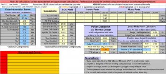
what's the problem with the spreadsheet?
I can see 4r0 load and 59W @ 1% distortion from +-25.4Vdc.
The orange cell showing 1.04C/W indicates the chip is needing a lot of sink to stay cool.
The N/A in the cell directly below tells you the thermal resistance of the isolated package cannot get rid of the heat in the chip.
Am I correct in interpreting assumption4 that the chip is fixed with thermally conductive compound direct to the sink? What voltage is the sink at?
Add in the reactance of a real speaker and the chip is starting to run into real stress. Drop the impedance to 4ohm and 60degree phase angle for a severe speaker load and the chip will start cutting out if you try to get maximum power out of it on a PA type duty.
Use it for typical domestic duty where average output is below -20db ref maximum output (ie. 0.6W average =600mW)and the chip will stay cool enough.
This will require mid efficiency speakers, try 88db/W to 92db/W.
Use this amp to drive an 84db sub-bass and it will tell you it does not like it.
All that comes from reading between the lines in the datasheet and that orange cell in the spread sheet.
I get criticised for reminding folk that chipamps do not like low impedance loads. Who wants to put the alternative case today?
If you parallel two chips so that each thinks it is driving an 8r load then the heat problem virtually goes away. You still get 60W into the 4ohm load from the parallel pair, but at far less distortion.
Try changing load to 8r and then look at the parallel output.
Hi,
having downloaded that spreadsheet, I tried a few numbers.
Keeping the same 4r load, +-25.4Vdc & 25degC ambient.
I had a look at the graph of power dissipation (per double chip) when output averages -10db ref maximum. Pd=47W @ 6W+6W output.
That 1.04C/W sink will run at about 25+49=74degC.
Using Rth c-s of 0.5C/W, the case temperature will be near 100degC when the output averages 6W into 4ohms. I would suggest a sink with Rth s-a of about double the heat dissipation of the figure quoted in the spreadsheet.
6W is loud into 90db/W speaker, but may be the sort of level that might be attempted during a party (if the neighbours don't complain).
- Status
- This old topic is closed. If you want to reopen this topic, contact a moderator using the "Report Post" button.
- Home
- Amplifiers
- Chip Amps
- LM4780 Kit and Transformer Selection