Has anyone built this GEM amplifier by Graham Maynard?
http://gmweb2.net/Diagrams/GEM/GEM200.gif
I am planning to choose a good circuit for low efficiency and low impedance loudspeakers. I find this design very special and rather complex. Lots of large caps are used. But the designer claims it can deal with the back emf of the loudspeakers to control them very accurately. So I am posting here to seek for builders' comments on the performance of this circuit.
Graham is a very highly esteemed member of this forum, many of the schematics in circulation will not work without modification...
He has a newish circuit I am sure he'd love you to build... you will just need to hang on a few hours for the man himself to do his usual rounds...
He has a newish circuit I am sure he'd love you to build... you will just need to hang on a few hours for the man himself to do his usual rounds...
You are aware of this thread?
http://www.diyaudio.com/forums/showthread.php?s=&threadid=60546&perpage=10&highlight=&pagenumber=1
http://www.diyaudio.com/forums/showthread.php?s=&threadid=60546&perpage=10&highlight=&pagenumber=1
Um... Seem that it's really a great amp. I am gonna build it.
And I want to clarify that whether the two 8 ohm resistors at the outputs are necessary. If they and an 8 ohm loudspeaker are connected to the three outputs respectively, the load of the amp will become 2 ohms. So I guess the 8ohms are representing another two loudspeakers to show that this amp can drive 2 ohm load. Is that right?
And I want to clarify that whether the two 8 ohm resistors at the outputs are necessary. If they and an 8 ohm loudspeaker are connected to the three outputs respectively, the load of the amp will become 2 ohms. So I guess the 8ohms are representing another two loudspeakers to show that this amp can drive 2 ohm load. Is that right?
Hi Hajame,
I have added a link to the thread you link above.
As Carlos clarified above - there is no such thing as a universally 'best' amplifier, so don't assume that it will automatically sound better.
If some component values from the GEM were shifted to the Dx, and the same devices were fitted the Dx would sound more like the GEM (and vice-versa) but that is not what Carlos wanted; Carlos has designed a specific amplifier, so have I, so it must be up to a constructor to decide which they might manage to construct, and then which is the nicest to listen to.
Going to watch MotoGP now,
Cheers ........ Graham.
Hi Hajame,
Carlos is so fast with his constructions he became the first person to build a GEM after me.
He had some genuine bias and stability problems causing output device destruction which were not down to the 'Destroyer' himself; now cured.
Also the first circuit had a fractional mix of class-A and class-AB bias currents at the output stage which were audible; now separated.
Before anyone builds they should read this long page first.
http://gmweb2.net/Documentation/GEM...n Maynard.htm
In;-
http://gmweb2.net
The matching Mar07 buffer/pre-amp circuit has also been fully tested.
http://gmweb2.net/Diagrams/BUFFER/buffer8307.gif
Cheers ........ Graham.
Hi Graham!
I am a new member with some experience in constructing valve amplifiers LONG ago (I am 71 now!). I am intrigued by people's comments on the later version of G.E.M. 100W, and would like to try to build your new GEM.
Are there any other "aids" I can look for or receive from you, that can help me, please?
I mean Power supply suggestions, PCB layouts, any thing that can give me a little more support?
Your reputation is awesome on this forum, and I wish to benefit from your knowledge.
Nariman (nhwadia{at} gmail....com)
I built a pair of Graham Maynard's class A amps.from the Electronics World articles,then upgraded them to the GEM 25W.The sound quality was greatly improved,possibly due to the feed back resistors being reduced by a factor of 10 ( 10K/470R to 1K/39R),this gave a much "tighter" sound.
Without sounding too syncophantic,I think this is the best amp.I have built to date.My first being a Tobey-Dinsdale.
Many thanks,Graham,for an excellent design.
Without sounding too syncophantic,I think this is the best amp.I have built to date.My first being a Tobey-Dinsdale.
Many thanks,Graham,for an excellent design.
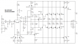
если удалить 4 выходных транзистора, то теряет смысл оставлять 5-й который служит для температурной стабилизации последних. Если его не удалить ничего плохого не произойдет
if you remove 4 output transistors, it makes no sense to leave the 5th one, which serves for temperature stabilization of the latter. If you don't remove it, nothing bad will happen.
if you remove 4 output transistors, it makes no sense to leave the 5th one, which serves for temperature stabilization of the latter. If you don't remove it, nothing bad will happen.
Last edited:
In memory of Graham
Graham really liked the sound of amplifiers with very low signal transit time (time Propagation Delay), in particular the sound of the JLH-69 class A amplifier.
Graham named his GEM amplifier after his father and used the LJH-69 amplifier circuit as a prototype.
Design goal: to make a more powerful and more economical amplifier while maintaining the properties of the JLH-69 amplifier
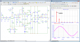
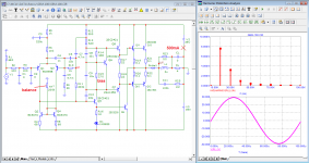
Here is one of the simplified versions of such an amplifier.
Graham really liked the sound of amplifiers with very low signal transit time (time Propagation Delay), in particular the sound of the JLH-69 class A amplifier.
Graham named his GEM amplifier after his father and used the LJH-69 amplifier circuit as a prototype.
Design goal: to make a more powerful and more economical amplifier while maintaining the properties of the JLH-69 amplifier
Here is one of the simplified versions of such an amplifier.
Attachments
I do plan on having someone tie a cross to my back (I have a nail allergy) and being whipped up the mountain for suspicions of tardiness. I am holding back because I haven't found "The One" guru to initiate the initiative. Though one contender comes to mind from post #950:
Some fixes:
Laplace transform and Fourier transform are two different animals, physically and mathematically. There are some fundamental difference in properties:
- the result of a Laplace transform is a holomorphic complex fuction, therefore is analytic, meaning that it can be represented as a power series, which the Fourier transformation in general can not. See below the relationship between Fourier transform and Fourier series representations.
- The Fourier transform is equivalent only to a bilateral Laplace transform, meaning integration from -oo to +oo, up to a 1/2PI multiplicative constant, through the s->jw mapping.
- the Fourier theorem, the foundation of Fourier transform, makes no assumptions about the periodicity of the transformed function. In fact, the Fourier transform of the step function does exist and can be used for any analytical purposes. You could consider the Fourier transform of a periodic function multiplied by a time limited function (AKA "window") however the resulting Fourier coefficients will now be complex numbers, so you won't be able to use the common harmonic analysis of the result, in the frequency domain.
A non periodic function doesn't have a Fourier series representation. Only a Fourier series representation is "harmonic", meaning that the frequency domain components are integer multiples of the fundamental frequency. What we usually consider a "Fourier transform" is the Fourier series representation of a signal extension to periodicity.
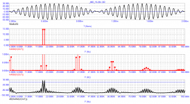
LTSpice (or any other simulator) doesn't know a damn thing about Fourier and Laplace when solving the non linear set of equations. The Fourier analysis is a post processing step, in which the algorithm assumes the solver output as a periodic signal and calculates the Fourier coefficients of the Fourier series representation. So if you take the first cycle sine, the simulator makes this very signal periodic and calculates it's spectra. This has absolutely nothing to do with (electric, acoustic) reality since the result does NOT extrapolate the same way in the time domain as well. That's what our dear Russian troll refuses to digest.
Bottom line, if you want to do a harmonic analysis of a time limited signal you have to extend the signal to periodicity and calculate the Fourier series through the Fourier coefficients. Otherwise, the "harmonic analysis" concept makes no sense.
We are using the Laplace transform to calculate a system response in the time domain. One can view the Laplace transform as an alternative to solving differential equations (which is what a simulator effectively does). This has nothing to do with "harmonic analysis" and a Laplace analysis of the simulator output is useless, since we already have the results of the time stepping solving algorithm.
...as a homage to your guru...
In the quest for a guru, perhaps as yourself:
There are four basic types of curved transfer function shapes of an amplifier being in relation to the midpoint of an input stimulus.
1. Upward expansive/Downward expansive
2. Upward compressive/Downward compressive
3. Upward expansive/Downward compressive
4. Upward compressive/Downward expansive
One and two generate third harmonics, three and four generate second harmonics. So the question is:
1. What is the wave shape and position of the non-linearity alone (in the time domain) resulting from a sinusoidal input stimulus that only generates a second harmonic in the frequency domain?
2. Under the same circumstances, that only generates a third harmonic?
I do plan on having someone tie a cross to my back (I have a nail allergy) and being whipped up the mountain for suspicions of tardiness. I am holding back because I haven't found "The One" guru to initiate the initiative. Though one contender comes to mind from post #950:
Just so you know, that was aimed at petr_ hence the suggestion for the name...
Syn08 could actually be a contender for a guru for me
")
//
Last edited:
- Status
- This old topic is closed. If you want to reopen this topic, contact a moderator using the "Report Post" button.
- Home
- Amplifiers
- Solid State
- The GEM amplifier