Hi, I want to make a linear regulated PSU for powering a LM3886 amp (~20w into 8 ohm). Space will be tight so a regulated supply is needed (since the big transformers needed for an unregulated gainclone will not fit, but the extra smoothing caps and regulators will fit ok). Since negative high current regulators are not common or cheap, I thought that was a good enough excuse to make my own using discrete components and a high voltage opamp (TLE2141).
Trying to keep it relatively simple and low part count. Not trying to get really low noise. But the idea is that even a basic discrete regulator with negative feedback will outperform a regulator IC.
I am at a cross road in the design. I've attached image of two regulators that should both give +18v, but I don't know which to use. The bottom one should have a lower drop out voltage. Apart from that are there any pros and cons to the two topologies?
The opamp is not JFET input so the 730R is there to balance the input impedances (2.7k // 1k = 730R).
Attachments
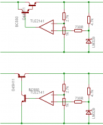
The first one is a good design (almost as efficient as an ideal linear regulator) but it has a high dropout voltage. The second design needs resistors in the collector and emitter of the NPN transistor at least, although a single resistor in the emitter can also work.mr.duck said:Hi, I want to make a linear regulated PSU for powering a LM3886 amp (~20w into 8 ohm). Space will be tight so a regulated supply is needed (since the big transformers needed for an unregulated gainclone will not fit, but the extra smoothing caps and regulators will fit ok). Since negative high current regulators are not common or cheap, I thought that was a good enough excuse to make my own using discrete components and a high voltage opamp (TLE2141).
Trying to keep it relatively simple and low part count. Not trying to get really low noise. But the idea is that even a basic discrete regulator with negative feedback will outperform a regulator IC.
I am at a cross road in the design. I've attached image of two regulators that should both give +18v, but I don't know which to use. The bottom one should have a lower drop out voltage. Apart from that are there any pros and cons to the two topologies?
The opamp is not JFET input so the 730R is there to balance the input impedances (2.7k // 1k = 730R).
Hi,
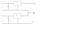
Another way to get bipolar voltage regulation using cheaper positive regulators is to use two seperate secondary windings on the transformer, make two single ended regulated voltages and connect them in series like two 'batteries'. I have modified some transiformers before by seperating the center tap into two seperate coils so as not to have to use :&: negative regulators and still be in the relm of the simple.")

Another way to get bipolar voltage regulation using cheaper positive regulators is to use two seperate secondary windings on the transformer, make two single ended regulated voltages and connect them in series like two 'batteries'. I have modified some transiformers before by seperating the center tap into two seperate coils so as not to have to use :&: negative regulators and still be in the relm of the simple.
Attachments
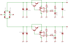
ok thanks. I'm going to use darlington config. I've attached schematic of the complete +/- regulator. If you spot any mistakes please let me know
I've put 100n ceramic cap across the power pins of the opamp. The power to the bottom opamp is round the right way, it doesn't show on the schematic but the pins are swapped over.
0v is attached to center tap of transformer.
Was I correct to put the 730R there to balance the inputs to the opamp?
output voltage, Vout = Vref ( R1 + 1 / R2)
Vref = 6.9v
R1 = 2.7k
R2 = 1k
Set for +/- 18v but I'll probably use 20-25v.
Attachments
- Status
- This old topic is closed. If you want to reopen this topic, contact a moderator using the "Report Post" button.