Hello all.
I am (also) trying to design a 12V to +/-55V dc/dc converter for amplifier use, with a power level of around 700W.
The prototype is up and running quite ok (although efficiency is only around 86% due to excessive transformer leakage inductance, I have to reduce it).
The thing is that I would like to add a current limit protection. But with the currents involved (around 60A), it is not practical to use current sense resistors without loosing lots of watts in them.
Another possibility is to use Rds(on) of the mosfets, blanking out the voltage drop between source and drain when the mosfet in particular is off. However, that's too dependent on temperature.
I am familiar with coilcraft current sensors, having used them with success in the past. But they are specified for 30A "only".
I was thinking on measuring the current to the 12V input to the transformer center tap. My idea is to split that connection in two thick and identical wires of the same length (2-3cm), passing only one of them through the transformer. That should theoretically produce a measurement of HALF of the total current, assuming that the other wires carries almost exaclty the same current. Do you think that this idea is practical/useful/crazy?
I don't need 0.1% precision in the measurement, but something useful for protection with an error of, say, 5-10%.
The same for the input fuses. I plan to use 2 x 32A automotive fuses in parallel at the input. Good or bad idea?
Thanks for your suggestions!
It is very easy to make your own current transformer. All you need is a suitable ferrite toroid with (say) 500 turns of this wire for the secondary, and the primary is simply the feed supply wire passing through the centre. You then load the secondary with a resistor. Obviously the ferrite (not dust-iron) must not saturate, but this shouldn't be a problem with a single-turn primary.
Ouroboros,
With 1-single turn primary, the flux is higher than with more turns, so it is the worst possible situation (B is inversely proportional to the number of primary turns).
Eva,
Very nice idea, but wouldn't it be difficult to measure such a small voltage drop (for 1milliohm track, 60mV max) in the presence of switching noise, etc, cleanly?
I get you when you refer to FET-input opams, such as TL071, 81, etc, for their extremely low offset voltage and input current, right?
I will try to do some tests with different load measuring with an oscilloscope and multimeter to see if there is really something to measure.
Best regards,
Pierre
It is normal in a current transformer for the primary to be a single turn. The resistive loading on the secondary, togther with the large step-up ratio means that the impedance presented by the transformer to the primary turn is negligable.
A current transformer is a special case, and it needs to be thought about differently from a normal transformer.
A current transformer is a special case, and it needs to be thought about differently from a normal transformer.
Pierre said:Ouroboros,
Eva,
Very nice idea, but wouldn't it be difficult to measure such a small voltage drop (for 1milliohm track, 60mV max) in the presence of switching noise, etc, cleanly?
Interference pickup is not that bad when you amplify the signal locally with very small PCB loops.
I get you when you refer to FET-input opams, such as TL071, 81, etc, for their extremely low offset voltage and input current, right?
No, I mean that these fet op-amps can sense voltages near or slightly above the positive supply rail, while most op-amps can't. On the other hand, conventional bipolar "single-supply" op-amps can only sense voltages near the negative rail (ground).
I will try to do some tests with different load measuring with an oscilloscope and multimeter to see if there is really something to measure.
Best regards,
Pierre
Test leads will pick up a lot of switching spikes and ringing. As I previously mentioned, the signal should be amplified locally before using it. It's not the same to carry a 0-60mV signal than a 0-6V signal.
I like to detect the voltage drop on the power input wire using a couple PNP transistors or a PNP transistor and a diode. Then there isn't a need for a separate power supply for an IC chip. The extra diode or transistor increases the sensitivity and provides temperature compensation. I wrap a sense wire around the power input wire.
Hi Luka. Thanks. ")
Here a rendition which doesn't have a resistor placed in series with the compensation diode junction. '7' is at the battery end of the power input wire obtained through the sense wire wrapped around it. '6' is at the power supply end of power input wire. The values of the components depend on the other circuitry. The end of the capacitor shown as being connected to '7' may be better connected to ground in many cases. Then you would more likely need that extra resistor. Another option is to make the extra resistor the one controlling when the circuit begins to operate instead of relying on the Resistance value of the input wire alone, which may be in the miliohm range, by the way. The resistor in series with the emitter of the active transistor may not always need to be in there.
Here a rendition which doesn't have a resistor placed in series with the compensation diode junction. '7' is at the battery end of the power input wire obtained through the sense wire wrapped around it. '6' is at the power supply end of power input wire. The values of the components depend on the other circuitry. The end of the capacitor shown as being connected to '7' may be better connected to ground in many cases. Then you would more likely need that extra resistor. Another option is to make the extra resistor the one controlling when the circuit begins to operate instead of relying on the Resistance value of the input wire alone, which may be in the miliohm range, by the way. The resistor in series with the emitter of the active transistor may not always need to be in there.
An externally hosted image should be here but it was not working when we last tested it.
The same for the input fuses. I plan to use 2 x 32A automotive fuses in parallel at the input. Good or bad idea?
Not a good ideea. Consider using a single 63A fuse.
Pierre said:Hello all.
I am (also) trying to design a 12V to +/-55V dc/dc converter for amplifier use, with a power level of around 700W.....................The thing is that I would like to add a current limit protection. .......... Another possibility is to use Rds(on) of the mosfets, blanking out the voltage drop between source and drain when the mosfet in particular is off. However, that's too dependent on temperature.......... Good or bad idea?
Thanks for your suggestions!
Pierre,
I ran across a neat schematic where the designer did indeed use the Rds(on) to measure the current drawn . This was for a DC-DC Converter for a Book PC in the car. I can't find it now, but I'm sure I posted here a while back. Do a "search" for BKi810 Book PC and see what you get.
Hope this helps,
Steve
Thanks, Eva, for the hints.
I measured the voltage drop between the +12V input and the transformer center tap and it CAN be measured (in fact it was more than 100mV at 37A input current). That, by the way, made me think that I should use thicker planes or copper!
I think I will use one of that specially designed Zetex current measurement chips.
My snubbers are, by the moment, 100nF+4.7ohm from each mosfet drain to GND, but they don't help too much as the transformer leakage inductance is too high and there's severe ringing. I must solve that first.
Re: Re: 12V DC/DC for amplifier. Current limiting?
Here's the schemo I mentioned............
N-Channel said:
Pierre,
I ran across a neat schematic where the designer did indeed use the Rds(on) to measure the current drawn . This was for a DC-DC Converter for a Book PC in the car. I can't find it now, but I'm sure I posted here a while back. Do a "search" for BKi810 Book PC and see what you get.
Hope this helps,
Steve
Here's the schemo I mentioned............
Attachments
Hello, N-Channel.
It is original: when the mosfet is OFF, you use the drain voltage to activate the transistor, that blanks out the measurement signal, and when it is ON, the drain voltage is Vds(on), that is equal to Rds(on)*Id, so you have a measurement of Id.
This principle is commonly called "Rds(on)-based sensing of drain current".
The problem is that Rds(on) is STRONGLY dependent on temperature (it can double from 25ºC to 80ºC in the junction).
It is good for some uses but not when you need a somewhat precise current limit threshold.
BTW: I have seen and used other variations of the same principle using only diodes: you can also blank the signal with a diode (cathode) connected to the mosfet gate, so when you have the mosfet OFF, your Vgs is nearly 0V, thus making a diode conduct and throw the measurement signal to 0.6V+GND. Its response is likely to be faster than using a transistor as it acts even before the mosfet has been turn fully off.
Sergio
Pierre said:Hello all.
I am (also) trying to design a 12V to +/-55V dc/dc converter for amplifier use
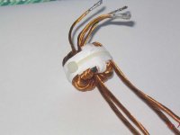
Nowadays i'm on the same mission
but mine will make 12V to +-40V.Last weekend i only managed to finish with the winding of the toroidal core for this project...
Here is an attached pic of it, i dunno why but i'm calling it the little piggy
Attachments
- Status
- This old topic is closed. If you want to reopen this topic, contact a moderator using the "Report Post" button.
- Home
- Amplifiers
- Power Supplies
- 12V DC/DC for amplifier. Current limiting?