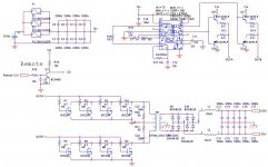
Here is the schematics of my SMPS that i'm going to use in my D-Class car amp for subwoofer.
Amp's output is going to be around 1 kW @ 4ohm, so SMPS has to do >1 kW
SMPS freq is going to be 35 kHz.
I would like to hear your input and improvements.
There ar few incorrect parts in this schema;
-I'm planning to use irf3703 fet, but those are only 30V devices, could there be a problem?
-Dual diodes i'm using are MUR1620CT and MUR1620CTR
-Transformer core is Amidon FT-240-77, Turns 4+4 and 22+22
-Inductor cores are Amidon T-130-3
Attachments
30V fets are a problem, the fet's see double input voltage (12 + 12 =24) fine for that but if voltage goes to say 14V then (14 + 14 = 28) no head room for small voltage spike. Find some 50 or 60V fets like IRFz44 , 70N06 or IRF3205, they have high current and 50 or more volts handling.
You could increase freq. to 100K clokc, 50K transformer, that would increase power output and decrease transformer size.
You could increase freq. to 100K clokc, 50K transformer, that would increase power output and decrease transformer size.
Ok, i'll find more suitable fet's...
Yes I could increase clock freq from 70 kHz to 100 kHz.
Actually when I decided to use 70 kHz clock freq was before bjt complementary pair and I was driving the fet's directly by sg3525. Ever since that freq has been haunting there")
Is there other suggestions?
This is what I'm also been wondering;
I'm using only 100n cap to filter the 12V going to sg3525. Would that be too little in these type of applications (SMPS)?
Yes I could increase clock freq from 70 kHz to 100 kHz.
Actually when I decided to use 70 kHz clock freq was before bjt complementary pair and I was driving the fet's directly by sg3525. Ever since that freq has been haunting there
Is there other suggestions?
This is what I'm also been wondering;
I'm using only 100n cap to filter the 12V going to sg3525. Would that be too little in these type of applications (SMPS)?
You should add in a cap of 220uF or greater in parellel with the 100nF cap, mostly for a stable supply line to the SG3525.
It looks like you've been looking at Mr. Rod Elliott's site. The resistors in the driver stage 6.8 Ohm's are usually missing in comercial designs, they tie the emitter and colleter together and then use 10 Ohm or greater gate resistors. Both designs seem to work so it's all up to you.(you do have a few less parts though)
Also, your missing your secondary side snubber, add one from ground to each rail.
I've been thinking of subber for secondary side. I will do the places for the components in to circuit board, but I'll test circuit first without it.
In my calculations, the subber in secondary side dissipates a lot of power, expecially for +-70 rails. I've also noticed that not all of SMPS that i've looked for uses it.
I looked at commercial 3 kW car amp for a while ago, and it seemed to have subber in secondary side, though resistors seemed to have a light brown tan
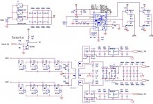
Here is an update (picture is quite crappy)
-470u cap in sg3525 supply line
-Snubber in secondary. 2x (1n & 330R)
-2 x 15V floating power supply for d-amp gate driving.
*Two extra secondary windings (18V)
*AC->DC MUR460 (mayby too rough device?)
*470u & 100n caps
*7815
*100n & 220u caps
any suggestions?
-470u cap in sg3525 supply line
-Snubber in secondary. 2x (1n & 330R)
-2 x 15V floating power supply for d-amp gate driving.
*Two extra secondary windings (18V)
*AC->DC MUR460 (mayby too rough device?)
*470u & 100n caps
*7815
*100n & 220u caps
any suggestions?
Attachments
sixtek said:Hi,
What about adding feedback for better regulation?
You mean feedback to sg3525? I left that off on purpose...
I have been competing in dB Drag Racing for many years, and that is the where the inthusia for building powerful car amps comes from.
In dB Drag, regulation is bad thing. Amps used there are "normal" car amps (yet powerful). What is abnormal is the way are used. In order to reach the max output power, the amps aren't used from a regular car battery and the voltage can go as high as 18V. That is why no feedback
. No, amps has hold on only 2 seconds Well, this amp will propably be never used in dB Drag, since in nowadays the smalest amps used in there are around 3 kW. Also the rail voltage is too high already to use 18v (amp output devices are irf640). Though I might have fun with it
¨luka said:Hi
Do you already have amps build? If so can I see them
For diods you can use mur15xx(1520,1560,...), they are 15A and very fast.
No, nothing to show yet.
I'd use those diodes, if i could get them on that supplier where the rest of the parts are coming from... I can call them and ask if they could order those...
sixtek said:Maybe you're right, but I never saw any car-smps without feedback (mostly they had optocoupler-feedback for ground isolation).
Thats intresting, I barely see any amps with feedback.
Then agin, I don't see many Pro amps either.
- Status
- This old topic is closed. If you want to reopen this topic, contact a moderator using the "Report Post" button.
- Home
- Amplifiers
- Power Supplies
- My SMPS schema