I started this thread over on Tubes Forum but think the relevant experts are probably here.
Being a cheapskate & being able to reuse material which would otherwise end up in landfill, this approach appeals to me.
It also gives chance to experiment - going dual mono - multiple supplies for filament/driving/final stages in an amp, etc
Hi all,
Just saw this article from 2004 showing how to convert a AT PC SMPS to regulated high voltage for use in Tube Power Amp
http://www.siliconchip.com.au/cms/A_102096/article.html
Only problem - you need to pay about $5 for access.
I just did and got the full article with schematics & description of mods
Quote from article:
"The circuit is capable of excellent performance. It maintains full regulation at up to 125W, with ripple at 2V peak-to-peak, or 0.3% at full power. This is quite acceptable, as most of the ripple is at twice the switching frequency (60kHz) and so is inaudible.
The 100Hz hum component is only 0.08%, which shows the excellent regulation of the TL494, since the rectified mains source contains 13% of 100Hz ripple at full power. Over-current protection is retained, with a LED added to indicate when it is active."
Final schematic below.
Has anybody tried this? How well does it work?
John
Attachments
I first saw this a few years ago, but was too cheap to give them the $5.00. So I just copied the pics and stared at them for a while. I like the idea, but since I'm not into valves, I would have no reason to do this.
On its technical merits, though, I don't think there would be anything wrong with this. if the author's prototype that appears in the pics is working, then it must be a valid design. I would say: go for it.
On its technical merits, though, I don't think there would be anything wrong with this. if the author's prototype that appears in the pics is working, then it must be a valid design. I would say: go for it.
Can you post the regulator part of it? (the TL494 area).
Last comment, Have fun winding that transformer for 700V output with enough insulation. (something I would be scared to try .)
.)
Also what is T3 for??? it's missing a secondary so it's not current transformer.
I would try to get that down a bit, may improve performance a bit, make that .08% ripple on the output drop even more.since the rectified mains source contains 13% of 100Hz ripple at full power
Last comment, Have fun winding that transformer for 700V output with enough insulation. (something I would be scared to try
.)Also what is T3 for??? it's missing a secondary so it's not current transformer.
ifrythings said:Have fun winding that transformer for 700V output with enough insulation. [...]
Also what is T3 for??? it's missing a secondary so it's not current transformer.
2 observations -
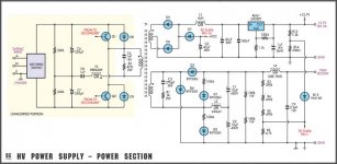
The rectifier for +700 is a doubler, which should make your work easier.
T3 is labelled "primary", so we can safely assume the driver part of the schematic has "T3 secondary" on it, and that it IS a current transformer (what else would make sense in that place?)
Hi all,
Thanks for coming back on this - I am trying to decide if it is worthwhile before embarking on a set of mods to high power supplies which is always scarry.
I intend to use it for +300V supplies so maybe the insulation considerations isn't as onerous as for +700V.
WIne&Dine is right it's a voltage doubler design.
Here are some more schema with the associated captions
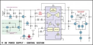
"Fig.2: the schematic of a typical control section based on the TL494 PWM controller. The only changes needed here are the removal of the over-voltage detection circuitry and the addition of an over-current indicator, based on Q7 and an LED."
Thanks for coming back on this - I am trying to decide if it is worthwhile before embarking on a set of mods to high power supplies which is always scarry.
I intend to use it for +300V supplies so maybe the insulation considerations isn't as onerous as for +700V.
WIne&Dine is right it's a voltage doubler design.
Here are some more schema with the associated captions
"Fig.2: the schematic of a typical control section based on the TL494 PWM controller. The only changes needed here are the removal of the over-voltage detection circuitry and the addition of an over-current indicator, based on Q7 and an LED."
Attachments
More quotes
"Great care must be taken with the transformer rewind to ensure primary to secondary isolation. In particular, make sure that each layer is completely covered with the tape, right up to the shoulders of the former, so that turns from different layers can not touch.
Except where noted, there should be no gaps between the start and finish of a layer and the shoulders of the former. This ensures that wire from the next layer can not creep into the gap and potentially make contact with the preceding layer.
The HV secondary winding goes on first, using 28 SWG (0.4mm) enamelled copper wire. Three layers are required, producing 117 turns in total. For the 400V version, use three layers of 24 SWG wire instead, producing 75 turns in total. It does not matter if your winding is a few turns short. The inner layer is the "hotter" end of the winding. It must be connected to the third pin from the edge of the PC board on the secondary side of the former.
A layer of polyester high-voltage tape is used to insulate each layer. Suitable "3M" brand high-voltage polyester tape is available from Farnell (cat. no. 753-002). Note that this tape is 19mm wide, whereas the standard former requires 17mm tape. To obtain the correct width, stick strips about 10cm long onto a clean plastic surface (such as transparency film) and trim off 2mm using a razor blade and straight edge."
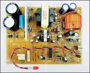
"A view of the reassembled PC board showing the newly rewound transformer (T1), HV filter inductor (L2) and HV capacitors (C1 & C2). L2 can be secured to the board using non-acidic silicone sealant."
"Great care must be taken with the transformer rewind to ensure primary to secondary isolation. In particular, make sure that each layer is completely covered with the tape, right up to the shoulders of the former, so that turns from different layers can not touch.
Except where noted, there should be no gaps between the start and finish of a layer and the shoulders of the former. This ensures that wire from the next layer can not creep into the gap and potentially make contact with the preceding layer.
The HV secondary winding goes on first, using 28 SWG (0.4mm) enamelled copper wire. Three layers are required, producing 117 turns in total. For the 400V version, use three layers of 24 SWG wire instead, producing 75 turns in total. It does not matter if your winding is a few turns short. The inner layer is the "hotter" end of the winding. It must be connected to the third pin from the edge of the PC board on the secondary side of the former.
A layer of polyester high-voltage tape is used to insulate each layer. Suitable "3M" brand high-voltage polyester tape is available from Farnell (cat. no. 753-002). Note that this tape is 19mm wide, whereas the standard former requires 17mm tape. To obtain the correct width, stick strips about 10cm long onto a clean plastic surface (such as transparency film) and trim off 2mm using a razor blade and straight edge."
"A view of the reassembled PC board showing the newly rewound transformer (T1), HV filter inductor (L2) and HV capacitors (C1 & C2). L2 can be secured to the board using non-acidic silicone sealant."
Attachments
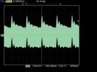
"The inductance of L2 is chosen so that current continues to flow for most of the "off" period at full load. You can see this effect in the SPICE simulation (Fig.3). As previously described, the use of an LC filter ensures that the output voltage depends on the duty cycle, as required for PWM control.
"100Hz hum can be seen on top of the 60kHz ripple and amounts to only about 0.6Vp-p.
Also "Primary side current is sensed using T3, a small current transformer. Its primary winding is connected in series with the primary of the main switching transformer. T3 employs a very large transformation ratio (n of about 180), combined with a relatively small resistance across its secondary winding
Attachments
wine&dine said:
The rectifier for +700 is a doubler, which should make your work easier.
I missed that area of the schematic, that would help with winding too.
T3 is labelled "primary", so we can safely assume the driver part of the schematic has "T3 secondary" on it, and that it IS a current transformer (what else would make sense in that place?)
Your correct agin, as you said nothing else would make sense here.
jkeny
thanks for the regulator part of the schematic, answers a lot of my blind questions.
- Status
- This old topic is closed. If you want to reopen this topic, contact a moderator using the "Report Post" button.
- Home
- Amplifiers
- Power Supplies
- modyfing a pc switchmode for B+