>I'm sorry, but I still don't see any reason to use flipping for halfbridge instead the full bridge 200VDC invertor, because mosfets, diodes and caps will use same type and quantity
I think you mean 340VDC bridge not 200VDC. 120VAC = 2*120*1.414 (peak-to-peak). Its much safer to do 170V to -170V than to go 0 thru 340V. You would still need to boost the input voltage at 170VDC (full bridge rectified) to 340VDC which adds complexity and decreases efficiency. Plus your only using half of the rectified voltage for half of the cycle. The Bottom half of the cycle would probably need to be switched twice as fast as the top half of the cycle in order to get good regulation, which would complicate the design.
>flipping will have outstandingly poor precision and nothing more
Not really. It flips on a zero voltage crossing boundary. There should be no distortion when it flips because its switched when the AC output voltage is at zero volts.
>I'm sure, that taking feedback from the outlet directly, it is most important feature for AC regenerator
The feedback loop just need to regulate the voltage for half on a sine wave and the flipping bridge does not affect precison. There are no components after the bridge to distort the feedback voltage. The feedback input would be taken after the output caps and inductors, behind the flipping bridge.
FWIW: This techique is commonly used for PWM controlled UPS systems.
TechGuy, unbelievable, but i go to 3th attempt to explain a BTL mode (BTL=H-brige=Full-bridge PWM invertor).. google it please, or just trust me -even 170VDC enough to poduce 120VAC RMS, but we take 170VDC+18% for insurance, hence, your 340VDC (i've used around 380VDC, BTW Eva [diyaudio.com member] too ) enough for 230VAC RMS regeneration. H-bridge already have "intelligent" (in the feedback loop) flipping mechanism, but not BANG-BANG flipping around zero crossing. In the Uninterruptible PS systems several percent of the distortion it's ok, but our task is the high precision audio (diyAUDIO.com), and i see no logic to buy regenerator ($1500-3000) with THD 3%, if i can see 3% from the wall. Nice if your "flipping bridge does not affect precison", however, the switchers must have zero Ohm On_state (and 0nS response), i can't find such yet. Well, how i told above, only feedback from the outlet can give precise sine regenerator in the real world.
Hi
Originally posted by TechGuy
To further reduce noise and distortion, a synthesized sine wave can be generated to reduce or eliminate harmonics. Google for "Magic sine waves" for more info.
Hope this was useful.
I have been using this approach to power my turntable for 10 years. It works well and makes a major difference in the clarity of notes.
I tried it on a class A pre amp and found little if any change in performance against a regulated power supply for the pre amp.I later used this approach to power a cd player and found a modest improvement.
Don
I'm not sure what the difference is between an AC Power "conditioner," "filter," or "regenerator" ... but I have a congested electrical environment in my listening room with a computer on the same circuit as my amps and source equipment. The switching power supply adds a lot of noise to my power and you can hear it in the preamp and the amplifiers.
What do you guys think about using Auricaps to filter AC current? They are not AC rated, but apparently there are some manufacturers/assemblers who use them and claim them to be effective in clearing up muddy AC power.
Example:
VH Audio - Hot Box
What do you guys think about using Auricaps to filter AC current? They are not AC rated, but apparently there are some manufacturers/assemblers who use them and claim them to be effective in clearing up muddy AC power.
Example:
VH Audio - Hot Box
If you need mild AC filtration, the filtered version of the Hot Box is outstanding.
An optional power filter upgrade may be purchased for an additional $99.99. The filter consists of two .47 uF 600V Auricaps per receptacle (4 caps total) connected between line and neutral. Simply order the Hot Box, and then order the filter upgrade for $99.99. --From vhaudio.com
Does anyone know how to build a Power Line Conditioner?
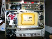
this is my homebuilt power conditioner....it has emi filters, surge protectors, and isolation transformer.

IVX said:TechGuy, unbelievable, but i go to 3th attempt to explain a BTL mode (BTL=H-brige=Full-bridge PWM invertor).. google it please, or just trust me -even 170VDC enough to poduce 120VAC RMS, but we take 170VDC+18% for insurance, hence, your 340VDC (i've used around 380VDC,
OK, now I see what you're suggesting. I completely miss- interpreted your early posts. Sorry about that!
What I had proposed is to let the PFC controller synthesize half of a sine wave so that it would compensate for voltage sags and over voltage conditions. The feedback loop for the PFC controller would be configured so that instead of generating a fixed 170VDC, it output half a sine wave. The output would be tied a Flipping bridge. In this configuration, there would be no need for an additional PWM bridge. I assume you though my intention included a seperate Bridge for AC synthesis, which I did not. I apologize if that was unclear.
I suppose in your suggestion, the PFC would output a fixed 170VDC and a separate PWM controller would be used to synthesized AC waveform using a BTL. Although additional switching losses would occur because of the ripple current across the output inductors and caps (proportional to the BTL switching freq.) during low output current loads (I'm assuming variable load s). Assuming this was your intention, there would be no significant difference in switching parts between what I have proposed and your suggestion.
I don't see an easy way to replace the PFC to provide voltage boost during voltage sags, with a BTL. If you have a better way, I am all ears.
IVX said:but our task is the high precision audio (diyAUDIO.com), and i see no logic to buy regenerator ($1500-3000) with THD 3%, if i can see 3% from the wall.
[/B]
FWIW: I believe the thread was started on the idea of protecting electronic equipment from under and over line voltage conditions in a region (South Africa) that has low quality power. I am not sure if very low THD was a concern (for a non-audio application) and efficiency was important. In the case of minimizing THD over efficiency, the suggestion you have proposed would be a better. Although this is an "audio" forum, there is lots of discussions about non-audio SMPS applications.
PS. Another idea that might reduce distortion and improve efficiency would be to use PFC interleaving, just add more time and $$$.
Take Care!
mjraudio said:What do you guys think about using Auricaps to filter AC current? They are not AC rated, but apparently there are some manufacturers/assemblers who use them and claim them to be effective in clearing up muddy AC power.
It probably will help, but don't brace yourself for large change. I buy Elgar conditioners ... active units that buck or boost line voltage on a feedback mechanism that compares output voltage against a reference sine wave. I think the original cost of these beasts is $6000, and I usually pay little more than $100. They're rated at some god awful 30A peak, with output distortion 0.2% max for 10% incoming distortion.
Anyways, because they're so cheap, I've been experimenting running them in series. Putting one into my system made a very nice difference. Two in series made another nice difference. Three in series yet another. Putting an isolation tranformer before the lot further improved matters. Putting a balanced AC transformer between Elgar 1 and Elgar 2 also improved things. Take it from my extreme (and quite enjoyable) experiment: line borne noise is insidious.
suppressing noisy PSU
Hi,
if the PSU proves to be injecting noise into the nearby analogue stages then it can only be coming from two directions, through the air, or through the mains wiring.
Put the isolator/conditioner/filter on the supply to the noisy PSU. The output of that noisy PSU should be unaffected by this change and you only have to filter one supply.
All the audio around the house should now be quieter.
Give it a try and tell us if it works.
TechGuy said:
OK, now I see what you're suggesting. I completely miss- interpreted your early posts. Sorry about that!
If you completely miss- interpreted me, it's probably my mistake -english isn't my native, and currently i'm unwell (seems flu), so, about few days i'm more stupid then usual.
") Yeah BANG/BANG flipping will add a little bit efficiency, and little bit reduce cost (2 vs 4 good mosfets required), but the precision will be dramatically worse, that's exactly why i not considered this technique even, when we started developing our own regenerator. And yes, i don't know other way to boost rectified voltage, PFC only, but it's good feature as well, especially for low voltage standards (USA, Japan) due to short&bigger current pulse of load.
Yeah BANG/BANG flipping will add a little bit efficiency, and little bit reduce cost (2 vs 4 good mosfets required), but the precision will be dramatically worse, that's exactly why i not considered this technique even, when we started developing our own regenerator. And yes, i don't know other way to boost rectified voltage, PFC only, but it's good feature as well, especially for low voltage standards (USA, Japan) due to short&bigger current pulse of load.Actually there is a lot offers of the cheap UPS on the market, it's 100% available in the South Africa too, however, do you can recollect the name of the really precise AC regenerator?
serengetiplains said:
It probably will help, but don't brace yourself for large change. I buy Elgar conditioners ... active units that buck or boost line voltage on a feedback mechanism that compares output voltage against a reference sine wave. I think the original cost of these beasts is $6000, and I usually pay little more than $100. They're rated at some god awful 30A peak, with output distortion 0.2% max for 10% incoming distortion.
@serengetiplains: What model are your Elgar units? If they can deliver 0.2% THD output from 10% THD input, that is mightily impressive for a ~$100 AC supply!
And to think that people actually spend thousands on this.
Also, how would I benefit from using Auricaps to "filter" AC current? Would that help to create a smoother sine wave? Or simply filter out "noise?"
@all: What do switching power supplies do to AC power in a circuit? If I have my amplifier plugged into the same circuit as a computer with a switching power supply, how will that psu add noise to my ac current?
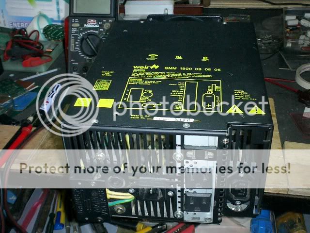
MJR, I use the 6006B. They're ugly beasts, so I stuff them in my basement and run dedicated lines from them. They come with a fan that would push a boat across a swamp. I don't run much current through them (no Krell class A stuff in my system) so I disconnenct the fan entirely. The units I've purchased tend to be from the 1980s, so are good candidates for capacitor upgrades. They're otherwise built like a tank using best-quality components. The Accuphase conditioners use the same buck/boost principle, which parenthetically gives you something like 85% efficiency (hence the ability to disconnect the fan).
A capacitor across your mains merely provides a slightly lower impedance for certain (high) frequencies. Some portion of those high frequencies (think voltage divider) will take that path. The Elgar units, for their part, place a capacitor across their output for that very reason.
A capacitor across your mains merely provides a slightly lower impedance for certain (high) frequencies. Some portion of those high frequencies (think voltage divider) will take that path. The Elgar units, for their part, place a capacitor across their output for that very reason.
serengetiplains, Can I ask where you find these and at such decent prices. I saw a few on ebay with low starting bids. However, looking around at surpluss vendors and places carrying them used, they are getting premium, between 500 and 1500 dollars for them.
Any chance you would be willing to take a picture of the insides of one so we could see whats inside them. For the most part line conditioners seem to use some form of inductive or capacitive filtering, an isolation transformer, balanced power transformer, or outright regeneration. I've always wondered how they lower the distortion to such levels, what type of filtering is used, and how it compares with some of the DIY versions out there.
Any chance you would be willing to take a picture of the insides of one so we could see whats inside them. For the most part line conditioners seem to use some form of inductive or capacitive filtering, an isolation transformer, balanced power transformer, or outright regeneration. I've always wondered how they lower the distortion to such levels, what type of filtering is used, and how it compares with some of the DIY versions out there.
If the purpose of a mains conditioner is to supply a relatively constant voltage to the load and incidentally reduce noise, transient and EMI feed through, why is distortion important?
Earlier ferro-resonant regulators were mentioned, they are sort of reasonable used and almost indestructible. Their greatest sin is output distortion. I think most of these distortion products are odd harmonics leading to a sine wave that is somewhat flat topped.
I would think a flat topped sine wave is actually a desirable shape for the rectifiers in the downstream equipment, longer conduction angles for the diodes leads to lower impedance and less heat (‘course the ferro-resonants run hot as all get out).
Anyway am I missing something? Within limitations of downstream transformers, purity of the sine wave as long as there are no high frequency edges seems un-important.
Ferro-resonants do have one other sin, they tend to emit accoustic hum, you won't want them in your listening room.
PJ, an Elgar 6006B is now for sale on eBay. $50. Just have to wait a few weeks or months as they regularly appear.
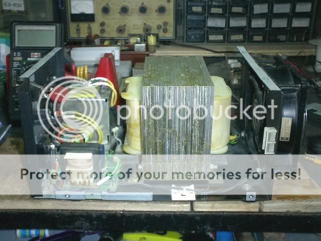
The Elgars regenerate the AC, in a manner of speaking. At the core of their operation, so to speak, is a large EI isolation transformer weighing in the vicinity of 60 lbs.). Atop the high-V secondary sits a class B amplifier that increases or decreases the sine wave voltage, in effect to cancel non-60Hz products ... this is called a buck-boost topology, and is the very same topology used by the Accuphase brand of conditioners (which sell for $12K new or something). The buck-boost topology is overall quite efficient as most of the 6006B's power is taken from the secondary itself, hence 85% efficient.
Hermanv, a harmonic = a non-60Hz frequency. Noise = a non-60Hz frequency. A harmonic = noise, give or take? Seems reasonable to me. Add to this the observation that Elgars (PS Audios, Accuphases) work and one has a basis for thinking, yes, you're probably missing something.
Attachments
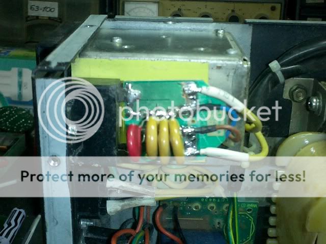
BTW, in the attached picture above, the class B amp is on the bottom, with one of the Elgar's two rows of heat sinks visible. The isolation transformer is in the middle. Control circuitry is at the top right in three removable circuit boards (very handy for upgrades). Pay no attention to the messy alterations, the product of my mucking about.
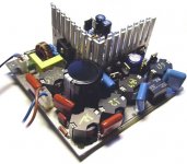
AAH, it's pretty funny words game, really my almost_diy regenerator, so to speak, is a buck boost too! If more truly, there are boost converter PFC and synchronous buck, but it's completely different topology yet, without any visual similarity. BTW, if 85% efficiency, why so huge devices (e.g. my PCB 5.5"x5.5" at 95% efficiency)?
Attachments
- Status
- This old topic is closed. If you want to reopen this topic, contact a moderator using the "Report Post" button.
- Home
- Amplifiers
- Power Supplies
- Power Line Conditioner