An externally hosted image should be here but it was not working when we last tested it.
An externally hosted image should be here but it was not working when we last tested it.
An externally hosted image should be here but it was not working when we last tested it.
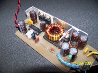
Transformer EI33 --10x0.5mm prallel 20 tour
PCB view and print program
Download
PCB SCHDownload
Gev,
Looks great. Some questions:
Is this a flyback or c.t. push-pull?
Is it isolated or non-isolated?
What is your application?
Powering a laptop from the car?
Xfmr core/bobbin look familiar: are these from an old AT/ATX psu?
Also, the yellow transformer tape looks familiar. Did you re-use the tape from the old xfmr or buy new tape. I have been looking for this tape, but can't find it anywhere. If you bought it, please say where. Thanks!
BTW, I have built many laptop DC-DC converters using just an LM2587 5 Amp SimpleSwitcher IC. Recently learned to synchronize two of them for increased current output.
Steve
I ask these questions, because I have contemplated doing a DC-DC Boost converter using discrete components rather than an IC swtiching chip. Have lots of experience with those, and I wanted to expand my horizons a bit. I am glad to see someone has successfully done it, and wish to compliment your work.
Couple more questions:
1) Which controller chip? UC384X? Voltage-mode? Current-mode?
2) What is its switching frequency?
3) Have you tested it for EMI/RFI?
I am very curious on your results. Again, Nice work.
Steve
Couple more questions:
1) Which controller chip? UC384X? Voltage-mode? Current-mode?
2) What is its switching frequency?
3) Have you tested it for EMI/RFI?
I am very curious on your results. Again, Nice work.
Steve
Guys-
Thanks. I suspected a '3843 because of the 12V operation. 130-170kHz, huh? I would be curious to see the switching losses at that frequency range. I was planning a more modest 50-100kHz. Voltage-mode? I thought the UC384X series were current-mode controllers. How did you get it to operate in voltage-mode?
I just finished troubleshooting a 2-F interleaved DC-DC Uppie from 12V to 19-20V using an SG3525, two MTP75N06s switching a T-80-26 (yellow-white) core (24T+24T) into an MBR2545CT at 100kHz. I will post pics & schemo later today. Basically, I gutted a Dell AC-DC Laptop converter, salvaged the Nichicon 470mF 105C caps, heatsinks, and the green LED for the new circuit.
I got the idea for a 2-F interleaved topology from an article in the NOV 2004 QST. It had a 13.8V voltage booster for transmitting full power (100W) on battery for radios whose input voltage range is very picky, and cannot go below 12V.
Input is good down to 8V (the '3525's UVLO threshhold is 6-8V), and the current should be limited by only the guage of the wire, the diode rating, and the Drain current of the two MOSFETs. I haven't tested it on a load greater than 1 Amp because my lab benchtop PSU is good for only 1.5A per channel before current-limiting sets in. I plan on testing it with my big 30A PSU later this week.
Gev-
I like the test stand you made (swtiches & lights on a perfboard). I think I will construct something similar so I can get a visual effect on the switcher's performance.
steve,
i saw that article in qst also. thought is was interesting,.
i have built a little twelve volt generator out of a 3.5 hp briggs engine and an 10si 105 amp gm alternator. puts out about 75 amps at 13v.
cheap and easy, starts every time a later cs alternator or larger si alternator will make more current, but the si are cheap, i have time in it not a cent.
even new the alternators are around 45 bucks. a horz or vert shaft motor works.
I'm (slowly) working on one of those too.. 
More info on this site:
http://theepicenter.com/tow02077.html
More info on this site:
http://theepicenter.com/tow02077.html
Guys,
this is what I have been working on for the last two years! Paralysis by over-analysis. I have two engines: 3.5HP B&S vertical shaft w/electric start (I have to be the first kid on my block to say I have a DIY electric-start Generator!), and a 6.0HP B&S OHV vertical shaft w/pull- & electric start. Both from eBay, both new & unused.
Gen 1 (6HP): will be driving a Delco CS-144 140A alternator (also from eBay) into a 90Ah deep-cycle battery with a Xantrex Pro-Sine 1800 Inverter (Again, from eBay). Good for Field Day or whenever I need QUIET power anywhere, like showing movies in the park after dark, or for camping. Oh yeah, I will be able to jump-start dead cars, too.
Gen 2 (3.5HP): This will drive another CS-144 140A (New, $35.00 on eBay) into a pair of 40Ah Union deep-cycle batteries. This one will be mainly for 12V applications, like Field Day, jump-starting, or where no 120VAC will be needed.
Both engines have 6V motors for the starters, with small alternator coils near the flywheels to recharge the batteries. All engines, alternators and batteries were new at time of purchase. Forgot, one of the guys in our ham radio club works for Detroit Edison, and has access to all kinds of batteries, 6V & 12V. If shipping wasn't so darned expensive, not to mention the HAZMAT issues with shipping batteries, I would send some your way.
James- I contemplated doing a 10SI for the 3.5HP, but I actually stumbled across the second CS for cheaper than the SI.
I have done alot of websearches for "DIY homemade Generator", "Homebrew Generator", etc., and have downloaded many pics of them. The most info comes from theepicenter.com, but also check out NS8O's webpage. It appears he is a welder, and he makes his own custom made frames for generators. Do a Yahoo! or Google search for NS8O.
Luka,
I did do a buck converter, but not with the SG3525. Mostly with Nat Semi SimpleSwitcher ICs.
I know I promised pics and a schematic of my 2-F boost converter, but it has been crazy around here. I will post them ASAP, as well as the "progress" I am making on both gen sets.
Cheers Everyone,
Steve
Luka,
Check out these datasheets from National Semiconductor:
http://cache.national.com/ds/LM/LM2576.pdf (3A Buck, 52kHz)
http://cache.national.com/ds/LM/LM2596.pdf (3A Buck, 150kHz)
http://cache.national.com/ds/LM/LM2677.pdf (5A Buck, 260-400kHz)
http://cache.national.com/ds/LM/LM2678.pdf (5A Buck, 260kHz)
Also, I stand corrected: I did do a Buck a long time ago using the LM1524 driving a BIG P-Channel MOSFET, but I do not have it in any schematic CAD package. I have never done a Buck using an N-Channel, but if I were to do one, I would have a Charge-pump to supply the higher-than-the-rail voltage needed to properly drive it..
Here is an interesting Application Note from the old Unitrode on using an N-Channel as a High-side switch in a buck. It uses a UCC3803, but I suspect it would work just as well with any of the UC384X chips.
Steve
Attachments
How much current ya' drawin'? If less than a couple a' amps, then try these:
1) LM2592HVS-ADJ (150kHz, 2A, 65V in max, adjustable output, surface-mount)
2) LM2592HVT-ADJ (same as #1, but 5-Pin through-hole TO-220)
3) LM2576HVS-ADJ (52kHz, 3A, 65V in max, adjustable output, surface mount)
4) LM2576HVT-ADJ (same as #3, but 5-Pin through-hole TO-220)
-----OR-----
You could use an SG3525 like Fig. 10 of the Datasheet for the SG3525A from ONSemi. I would use a zener regulator to drop the 40V down to, say, 15V for powering the '3525's +VCC & +Vc pins. Then use either a BIG PNP or P-Channel as the switch.
Good suggestion for P-CH: RFG60P05E from Harris. 50V DSS (OK for 40V), 60A I(d), and Rds(on) of only 0.026 ohms! Have them sample you some, or better yet, send me email and I can send you some, as I have a boatload of 'em here just gathering dust.
- Status
- This old topic is closed. If you want to reopen this topic, contact a moderator using the "Report Post" button.
- Home
- Amplifiers
- Power Supplies
- 12v=19v 4,7A dcdc