and to add another question, suppose I get a different powdered iron core (different size), would it be perfectly fine to just wind it to get the same inductance value? operation not affected? (assuming I get the same or bigger core)
and also, you mention 24T bifilar wound on the core. is this 12T + 12T or 24T +24T?
I would like to do a TL494 version but realized I already had a couple of 3525's sitting here so I guess it wouldn't hurt to use them. besides, eliminating the drivers makes a little bit smaller PCB.
and also, you mention 24T bifilar wound on the core. is this 12T + 12T or 24T +24T?
I would like to do a TL494 version but realized I already had a couple of 3525's sitting here so I guess it wouldn't hurt to use them. besides, eliminating the drivers makes a little bit smaller PCB.
DJ-
Go with the SG3525 then. And its outputs are good for +/-400mA, so driving a pairof TO-220 MOSFETS shouldn't be a problem withour a drive buffer. You will have to alter the number of turns if you're using a different size. Also, keep in mind how using a different material will affect things. Amidon Associates has a good datasheet for all their products, and the A(l) values for the different sizes/materials is on there. The basic equation for calculating the number of turns for powdered-iron toroids is as follows:
..............._____________________________
N= 100 x \/[(L(mH) / A(l) value].
Or, in plain English, the number of turns will be the square root of the desired inductance in microhenrys divided by the A(l)value, all multiplied by 100.
Example: for a 22mH indictor on a T-80-26 core, you will need-
................__________
N = 100 x \/22mH / 590 = 19.31T (Round this up to 20T).
Luka-
Not too sure. Is 13.8 your output? I assume this is a boost and not a buck, right? If it is a boost, then, I don't have the design procedure in front of me, but you could use the design procedure from Brown. Also, if it is a boost from 10-12V to a stable 13.8V, you need to give the NOV 04 issue of QST a look at. Another blogger here, dkempaii, wrote an article on just that. He is an Amateur Radio operator, and his project was for transmitting at a full 100W from a single 12v car battery while maintaining a steady 13.8V, even as the battery discharges.
His circuit uses an SG3524 (though a '3525 should work too), to drive a pair of N-CH TO-220's using a conventional (meaning out of a pc supply, and NOT a 50/60Hz one) transformer with center-tap primary & center-tap secondary, rectified, filtered, and the whole nine yards. The trick here, though, was the center-tap of the secondary joined the center-tap of the primary going to +V(in). Consequently, all the secondary side saw was the difference between 13.8V and whatever the incoming voltage was, ~1-3V. Anway, go to the
ARRL's website and download that issue. His pc boards are available from a US distributor of components for many of QST's projects. FAR Circuits is the place.
I have an LC meter and I think that will be very handy. I have a few cores here where I already have written the AL value on them after measuring. I will need 33uH then.
although what type of cores are those with green/red paint on them? I have a couple and would be nice to know what they are. with their AL values, looks like they are powdered iron too? I see them used in motherboards I think for the 3.3V supplies.
I will need 33uH then. although what type of cores are those with green/red paint on them? I have a couple and would be nice to know what they are. with their AL values, looks like they are powdered iron too? I see them used in motherboards I think for the 3.3V supplies.
Luka-
What do you mean? Like waveforms? I don't have the capability of transferring my readouts to computer. If I do, I am unaware of it. Anyway, if waveforms are what you're looking for, I will see if I can gin something up.
As for the 40V>13.8V converter, how many amps do you need? Do you want input-output isolation? If so, then use a transformer, either E-I or toroid. If not, then depending on the desired output current, I would choose either a T-130-26, or a T-200-26 powdered-iron ferrite. If you're using the MC33025, then I would make use of the 2-F topology because the '33025 has dual outputs. There are alot of datasheets out there on polyphase buck converters. I would go with a 100kHz clock for 50kHz on each output.
DJ-
Not sure what red-green cores are. Amidon Assicoates has the color code on their datasheets. If I see it later today, I will look it up.
What do you mean?
Like waveforms? I don't have the capability of transferring my readouts to computer. If I do, I am unaware of it. Anyway, if waveforms are what you're looking for, I will see if I can gin something up.As for the 40V>13.8V converter, how many amps do you need? Do you want input-output isolation? If so, then use a transformer, either E-I or toroid. If not, then depending on the desired output current, I would choose either a T-130-26, or a T-200-26 powdered-iron ferrite. If you're using the MC33025, then I would make use of the 2-F topology because the '33025 has dual outputs. There are alot of datasheets out there on polyphase buck converters. I would go with a 100kHz clock for 50kHz on each output.
DJ-
Not sure what red-green cores are. Amidon Assicoates has the color code on their datasheets. If I see it later today, I will look it up.
Hi guys, i'm new on this forum, but i have some simple switching power supply designed.
Did you considered that development software from Linear Technologies
SwitcherCAD III
http://www.linear.com/company/software.jsp
It's free, and it's VERY accurate and their chips are awesome and very easy to work with.
Did you considered that development software from Linear Technologies
SwitcherCAD III
http://www.linear.com/company/software.jsp
It's free, and it's VERY accurate and their chips are awesome and very easy to work with.
Hi Steve
By that i mean how does signal looks like just before inductor.
I have been looking at LM3485 and saw this picture
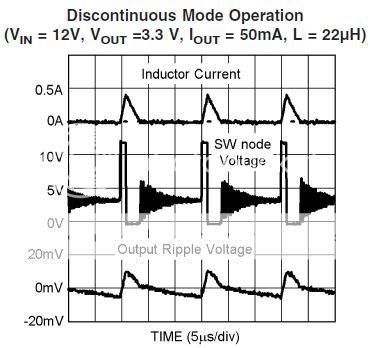
So that is why I asked this in hope to see yours.If you have scope and camera and can take some picture of waveform of your converter.
I would like to go for 75A (+/-25A depends on what I will be able to get, best would be 100A, but that is very high number of amps) for my converter, non-insulated.
Hi DRZ1
Well you can use it but you have to play with it a bit, I prefer real thing, where anything can go wrong.
By that i mean how does signal looks like just before inductor.
I have been looking at LM3485 and saw this picture
So that is why I asked this in hope to see yours.If you have scope and camera and can take some picture of waveform of your converter.
I would like to go for 75A (+/-25A depends on what I will be able to get, best would be 100A, but that is very high number of amps
) for my converter, non-insulated.Hi DRZ1
Well you can use it but you have to play with it a bit, I prefer real thing, where anything can go wrong.
I prefer real thing, where anything can go wrong.
me too. the cores that I can find here are always unknown so building the real thing is the only way to know if it will work.
Cant' find'em, but I'll look later todat. It's difficult sometime, though, because some manufacturers, like Amidon, do not color-code their ferrites, only the powdered-iron cores. And, I have seen several SMPSs main transformers use color-coded cores, leading me to believe that somehow, they are employing a powdered-iron ferrite in the main transformer.
But, as we all know, powdered-irons make a poor choice for this- thet are better suited to the energy-storage function of the inductor in a buck regulator. So this is where I get confused and start to believe that not all manufacturers follow the same color code.
But then, again, I challenge this thought with the fact that every AT & ATX box that I have either dissassembled or at leastr looked into, uses the familiar yellow-white core for the BIG cross-coupled output inductor.
Sorry to sufficiently muddy the waters here, but I will do my best to clear things up when I find the sheet.
Oh, yeah, and I will attempt to take pics of the waveforms, too.
And, I have seen several SMPSs main transformers use color-coded cores, leading me to believe that somehow, they are employing a powdered-iron ferrite in the main transformer.
me too. I have a scrap car amp that used a core painted blue. from the cores in my junk pile that I have tested. blue is not useful for a push pull design. better suited for boost converters.
But then, again, I challenge this thought with the fact that every AT & ATX box that I have either dissassembled or at leastr looked into, uses the familiar yellow-white core for the BIG cross-coupled output inductor.
me too. and from my scrap pile, they are all powered iron.
Let me guess- your scrap car amp is a red-heatsinked Rockwood "Detanator", right? The misspelling of "detonator is deliberate on the manufacturer's part.
I have that same core, and the windings were as follows: Pri: 4T +4T; Sec: 6T + 6T. Oscillator was a discrete multivibrator consisting of two small-signal NPNs, and a few Rs & Cs. Frequency of this free-running oscillator was about 66kHz (33kHz switching).
I have that same core, and the windings were as follows: Pri: 4T +4T; Sec: 6T + 6T. Oscillator was a discrete multivibrator consisting of two small-signal NPNs, and a few Rs & Cs. Frequency of this free-running oscillator was about 66kHz (33kHz switching).
N-Channel said:Let me guess- your scrap car amp is a red-heatsinked Rockwood "Detanator", right? The misspelling of "detonator is deliberate on the manufacturer's part.
I have that same core, and the windings were as follows: Pri: 4T +4T; Sec: 6T + 6T. Oscillator was a discrete multivibrator consisting of two small-signal NPNs, and a few Rs & Cs. Frequency of this free-running oscillator was about 66kHz (33kHz switching).
ummm. nope.
it's a pink heatsinked boschman and it supposedly puts out 300W x2 into 2 ohms/ch with 35V caps. 
the supply looks decent enough though. 5 IRFZ44's per phase with 6+6T in the primary. got it free as scrap and never powered it up. the supply is unregulated using a 7500 (similar to TL494) oscillator. and it has two 30A fuses.
I'm planning to use the chassis to build myself a 600WRMS class B monoblock.
luka-
WX here now is not so bad. Big ice storm over the weekend though. Many power outages in US Northeast from fallen trees and wires. Not our neighborhood, though. The old distribution point for our sub-grid was replaced/upgraded last year because of so many electrical utility customer complaints of frequent power outages. The power would go out when there was a slight breeze. Additionally, our residential area was at the very end of an industrial grid, and we would suffer the whiplash effect by being at the end of the line. We have since been re-routed to the residential grid in the square mile next to us. Our street used to sound like a dang campground with all the portable generators running!
OK, I found the color codes for powdered-iron toroids from Amidon Corp.'s catalog:
Mix Freq. Range
#26 u = 75 --
# 3 u = 35 50- 500kHz
#15 u = 25 100Khz-2MHz
# 1 u = 20 50kHz-500kHz
# 2 u = 10 2-30MHz
# 7 u = 9 1-25MHz
# 6 u = 8 10-50MHz
#10 u = 6 30-100MHz
#12 u = 4 50-200MHz
#17 u = 4 40-180MHz
# 0 u = 1 100-300MHz
I found a way to directly export waveforms from my Fluke Scopemeter to the PC, but it is so old that I can't find the software. I will look for it or contact Fluke for an updated copy. Soon as I load it, I will send pics.
DJ-
Boschman?? Hmm. I wonder who they're trying to confuse with name-brand "emulation"? That's like transposing Rockford and Kenwood to get "Rockwood" & "Kenford".
600W Class B, huh? Sounds cool. Will this be a sub-amp or full-range? If full-range, I would recommend a low-to-mid bias AB.
WX here now is not so bad. Big ice storm over the weekend though. Many power outages in US Northeast from fallen trees and wires. Not our neighborhood, though.
The old distribution point for our sub-grid was replaced/upgraded last year because of so many electrical utility customer complaints of frequent power outages. The power would go out when there was a slight breeze. Additionally, our residential area was at the very end of an industrial grid, and we would suffer the whiplash effect by being at the end of the line. We have since been re-routed to the residential grid in the square mile next to us. Our street used to sound like a dang campground with all the portable generators running! OK, I found the color codes for powdered-iron toroids from Amidon Corp.'s catalog:
Mix Freq. Range
#26 u = 75 --
# 3 u = 35 50- 500kHz
#15 u = 25 100Khz-2MHz
# 1 u = 20 50kHz-500kHz
# 2 u = 10 2-30MHz
# 7 u = 9 1-25MHz
# 6 u = 8 10-50MHz
#10 u = 6 30-100MHz
#12 u = 4 50-200MHz
#17 u = 4 40-180MHz
# 0 u = 1 100-300MHz
I found a way to directly export waveforms from my Fluke Scopemeter to the PC, but it is so old that I can't find the software. I will look for it or contact Fluke for an updated copy. Soon as I load it, I will send pics.
DJ-
Boschman??
Hmm. I wonder who they're trying to confuse with name-brand "emulation"? That's like transposing Rockford and Kenwood to get "Rockwood" & "Kenford". 600W Class B, huh? Sounds cool. Will this be a sub-amp or full-range? If full-range, I would recommend a low-to-mid bias AB.
hey, where are the colors? 
those brands are funny. they probably thought to use parts of the names to get the best (or probably, the worse) of both brands?
at that power range, I'm still considering a 600W @ 1ohm or two 300W @ 2ohm. still class B since I'm afraid a class AB will heat the chassis up very quickly. the chassis does have some fins but not enough to make me feel comfy with a class AB amp at that output. and I will most probably use it for sub duty.
sorry for the off topic.
those brands are funny. they probably thought to use parts of the names to get the best (or probably, the worse) of both brands?
at that power range, I'm still considering a 600W @ 1ohm or two 300W @ 2ohm. still class B since I'm afraid a class AB will heat the chassis up very quickly. the chassis does have some fins but not enough to make me feel comfy with a class AB amp at that output.
and I will most probably use it for sub duty.sorry for the off topic.
Luka,
Dunno. I think my Scopemeter is a Model 96, but I'm not sure. Will check at home tonight and let you know. However, it is missing software. It was a gift from a local power utility employee whose shop was upgrading the then-new Model 123 Scopemeter. They were ordered to "Throw them away". So, mine is on its way to the dumpster. It just might take 40 or 50 years to get there.
DJ,
UGH! Ithought I put the colors in there! They must've been edited out when I was editing that post. Anyway, here they are again, with proper color attached.
Mix Freq. Range
#26 (Yellow-White) u = 75 --
# 3 (Gray) u = 35 50- 500kHz
#15 (Red-White) u = 25 100Khz-2MHz
# 1 (Blue) u = 20 50kHz-500kHz
# 2 (Red) u = 10 2-30MHz
# 7 (White) u = 9 1-25MHz
# 6 (Yellow) u = 8 10-50MHz
#10 (Black) u = 6 30-100MHz
#12 (Green-White) u = 4 50-200MHz
#17 (Blue-Yellow) u = 4 40-180MHz
# 0 (Tan) u = 1 100-300MHz
Cheers!
Dunno. I think my Scopemeter is a Model 96, but I'm not sure. Will check at home tonight and let you know. However, it is missing software. It was a gift from a local power utility employee whose shop was upgrading the then-new Model 123 Scopemeter. They were ordered to "Throw them away". So, mine is on its way to the dumpster. It just might take 40 or 50 years to get there.
DJ,
UGH!
Ithought I put the colors in there! They must've been edited out when I was editing that post. Anyway, here they are again, with proper color attached. Mix Freq. Range
#26 (Yellow-White) u = 75 --
# 3 (Gray) u = 35 50- 500kHz
#15 (Red-White) u = 25 100Khz-2MHz
# 1 (Blue) u = 20 50kHz-500kHz
# 2 (Red) u = 10 2-30MHz
# 7 (White) u = 9 1-25MHz
# 6 (Yellow) u = 8 10-50MHz
#10 (Black) u = 6 30-100MHz
#12 (Green-White) u = 4 50-200MHz
#17 (Blue-Yellow) u = 4 40-180MHz
# 0 (Tan) u = 1 100-300MHz
Cheers!
- Status
- This old topic is closed. If you want to reopen this topic, contact a moderator using the "Report Post" button.
- Home
- Amplifiers
- Power Supplies
- 12v=19v 4,7A dcdc