Hi:
I hope I am in the right forum.
I want to build a mains filter, I read the article of Decibel Dungeon:
http://myweb.tiscali.co.uk/nuukspot/decdun/mainsconditioner.html
But I do not dare since I can not fully understand the diagram and I am a little afraid given my short experience and the power involved.
Does anybody could make some idiot proof , that’s me :-( , instructions?
Maybe we could ignore the screen since I do not think it is very important for the mains cleaning.
Of course I could go for another project as long it is efficient and sure, I also would accept a kit if anybody knows one good quality and reasonable price.
Thank you
Cosimo
It's a good thing to be cautious where the mains are concerned. Below is a schematic for a commercially available power line filter. some of the important things to take into consideration:
1) The capacitors have to be a.c. rated for your line voltage -- they are expensive -- polypropylene types are the preferred variety.
2) The filter should be contained in a metal box, preferably sealed. If you don't put it in a metal box, it's like going to the gym, working out and getting all sweaty, then putting on clean "trow" without showering.
3) Most of the parts can be scrounged from ATX power supplies !!!
I use Corcom filters -- easier than assembling the parts -- they work quite well (very well indeed). In fact, the price of a corcom filter is about what you would expect to pay if you had to assemble the parts from scratch.
An externally hosted image should be here but it was not working when we last tested it.
Hi,
the schematic in decibel looks complicated.
The difficult bit in the bottom half is just the indicator.
The top half is the suppressor.
Try building the top half only.
or do the very simple one that Jack posted.
You can add VDR or MOV in parallel to the first cap for extra spike attenuation.
BUT, CHOOSE your components CAREFULLY.
They MUST be rated for the correct voltage and duty.
Don't get your X caps and Y caps mixed up. It could be potentially LETHAL.
C3 MUST be Y rated caps
C1 & C2 are X rated caps.
Both types are self healing and tested to something like 2500V!
to anybody reading this post, or thinking about doing any mains filtering.
** please feel free to take some nice Yrated caps off my hands**
see my previous post in trading post.
http://www.diyaudio.com/forums/showthread.php?s=&threadid=88728
** please feel free to take some nice Yrated caps off my hands**
see my previous post in trading post.
http://www.diyaudio.com/forums/showthread.php?s=&threadid=88728
Here's a design that's been around for awhile and I put it in my CD player and it seemed to make an improvement.
Jon Risch's AC Filter
Regards,
Dan
Jon Risch's AC Filter
Regards,
Dan
AndrewT said:Thanks for the offer Hipcheck.
But, Scotland is a bit far away.
Scotland was here 2 weeks ago (wasn't St. Andrew's feast day this pst week?). Had a lovely time at the New York State St. Andrew's Dinner -- still can't get over the haggis with single-malt. The land of cakes --
Hi Jack,
maybe it felt like Scotland had moved to NY but, honest, some of us stayed at home to eat the oatcakes.
It was two day's ago, Thursday 30th Nov.
Our skool kids prepared a luncheon, dressed the tables, cooked a three course lunch, served it up and washed up afterwards for a group of invited guests, BRILLIANT.
The proceeds were split between the kids and a local charity.
Young Enterprise Scotland have a lot to answer for!
Hello all,
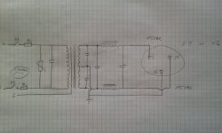
I'm currently designing a balanced mains filter and have a couple of questions/curiosities:
1. For safty I have a RCBO, where is the best place, before the primaries or after the secondary and/or before or after the filter network?
2. I will hooking up both digital and analogue sources and a few different types of amplifiers. Should these be filtered differently, if so, how?
Thanks in advance!
MV
Attachments
You'll need one on the secondary side; as it is now any short between L/N and ground will cause current to flow between that conductor and ground through a completed loop on the secondary side, while the L and N on the primary side will still carry the same amount of current (and not trip any RCD).
Ideally you'd want filters dedicated to the functions and power draws of each unit. Digital stuff tends to take lower power but throws out more noise (and at higher freqs) so would call for a multi-stage filter, not just a single CM choke. OTOH if you have a beefy poweramp its hard to give that much RF attenuation at higher power levels.
ok, the RCBO will be placed on the secondary side. On the primary side, can I get by with just one fuse?
I know extra filtering doesn't hurt, but don't most components already have elaborate filters build in? I always try to to add great filtering in the components I build so I am a little perplexed on the need for additional filtering.
@ abraxalito
I understand what you mean so I'll explain better with the following.
My "power centre" will have 10 receptacles, 2 unfiltered and the remaining eight a combination of filtered, isolated and isolated-filtered.
I will be connecting the following (what combination I had in mind):
1. CD Transport (only filter) )
2. Tube DAC (tx + light filter)
3. Tube Pre (tx + light filter)
4. Turntable motor (only filter)
5. Pre phono (only filter)
6. Amp 1 (Gain clone) (tx only, maybe light filter)
7. & 8. Amp 2 & 3 are a pair of tube mono blocks (tx only, maybe light filter)
For points 1, 4 and 5, will I need to add a switch to break ground and should these feed off the isolation tx?
Its quite unusual to see elaborate mains filters built in - quite the opposite in fact. To me its surprising how few high-priced items pay seemingly no attention to filtering at all. Perhaps the dealers call the shots though and want to gain bigger margins on filters, just as they do on cables?
I'd not fee the TT motor via the isolation trafo. The amount of filtering I'd recommend depends on how many other noisy appliances you have on the same mains - LCD and plasma TVs, PCs and the like.
I'd not fee the TT motor via the isolation trafo. The amount of filtering I'd recommend depends on how many other noisy appliances you have on the same mains - LCD and plasma TVs, PCs and the like.
RCBO and RCCB are mains electricity safety devices.
Residual Current Breaker means much the same as Earth Leakage Breaker.
If mains current is leaking to earth the device notices that the Live current is not the same as the Neutral current and opens the contacts to isolate the apparent fault (current leaking to earth).
These devices were not intended to be fitted to the secondary side of an isolating transformer.
Remember they measure the difference between the Live current and the Neutral current and when that difference exceeds a preset threshold the breaker opens.
Getting back to "mains filters" part of the topic, Jim Brown has some papers on the subject:
Audio Systems Group, Inc. Publications
Audio Systems Group, Inc. Publications
An externally hosted image should be here but it was not working when we last tested it.
These devices were not intended to be fitted to the secondary side of an isolating transformer.
True enough yet if you look as his proposed schematic, you'll see he's not using the isolating transformer for isolation, rather for balancing Line and Neutral to give 115VAC on both, but out of phase.
now he has two "live" lines, where there has only been one before, and a floating earth tied to a home power socket. That doesn't fills me with confidence.True enough yet if you look as his proposed schematic, you'll see he's not using the isolating transformer for isolation, rather for balancing Line and Neutral to give 115VAC on both, but out of phase.
- Status
- This old topic is closed. If you want to reopen this topic, contact a moderator using the "Report Post" button.
- Home
- Amplifiers
- Power Supplies
- mains filter