Hi all,
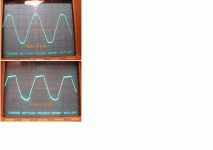
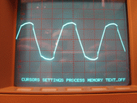
I use a toroidal transformer 50W, 230/15-0-15 VAC to built a 12 VDC linear PSU (2xdiodes + 2x4700 uF + LM338). When the transformer is open circuited the secondary AC output looks distorted like in the 1st pic, ie the transformer is a bit saturated and the DC outpout at the capacitors is then 20.5 VDC. When the transformer is loaded by 2.5-3 Amps at the capacitors side, the secondary AC outpout looks like in the 2nd pic and the DC outpout at the capacitors drops to 13.7 VDC. Is there any way to correct this saturation problem or the transformer is bad ?
I use a toroidal transformer 50W, 230/15-0-15 VAC to built a 12 VDC linear PSU (2xdiodes + 2x4700 uF + LM338). When the transformer is open circuited the secondary AC output looks distorted like in the 1st pic, ie the transformer is a bit saturated and the DC outpout at the capacitors is then 20.5 VDC. When the transformer is loaded by 2.5-3 Amps at the capacitors side, the secondary AC outpout looks like in the 2nd pic and the DC outpout at the capacitors drops to 13.7 VDC. Is there any way to correct this saturation problem or the transformer is bad ?
Attachments
Hi,
I am told that the first pic has now become the norm for our heavily loaded mains supplies with lots of capacitor input PSUs and electronic loads in our equipment.
I don't think there is anything wrong with your transformer.
The second pic shows a single diode (half wave) rectifier loading up just one side of the waveform. It is lots of these that caused the first pic.
You would be better using a bridge rectifier or a dual diode (full wave) rectifier. It puts less ripple into your load and it uses the transformer more efficiently.
BTW. you are overloading your transformer.
A 50VA 30Vac transformer has an AC output current of just 1.67Aac.
But the maximum continuous output from a capacitor input filter is just 0.83Adc. You are taking 3Adc!!!
Hi Andrew,
Thank you for the response.
The transformer is 50W not 50VA, but of course this doesn't change that much.
There were 2 separate secondaries of 15 VAC each.
I use a FW rectifier with CT. If I use a FW rectifier with a Bridge I ought to have the secondaries in parallel, which I dont like.
Actually the 2nd pic is taken from the 1st secondary (15V) that's why the waveform is not symmetrical.
You are right, the toroid is small for my application 12VDC/3~4 Amps DC. Do you think a toroid rated 90W (100VA) @ 1x16 VAC will be OK?
PS: I checked the distortion of the "sinusoidal" power line voltage with an AP instrument which "read" about 12%.....
The first waveform is perfectly normal, that's what you will find in almost every mains line.
The second waveform shows heavy transformer saturation, and that's only posible either because the secondaries are not identical or because whatever circuit you have attached to the secondaries suffers more voltage drop in one leg than in another for the same load (or both conditions).
Try to make the two legs of your half wave rectifier as similar between them as possible (same wire lenghts and gauges, same diodes, etc...) If that does not help then you should either try to compensate winding dissimilarities with added wire lenght in one of the legs, or better, you can parallel both secondaries and use full wave rectification. Note that when the transformer saturates it will not only overheat but it will also exhibit a very large voltage drop in the secondaries.
If you are concerned about losses in the diode bridge with full wave rectification, then try to get some low voltage high current Schottky diodes rated at 30V or 40V. They will exhibit roughly half the voltage drop of a conventional diode.
@ Eva
Please read my last post.
The 2nd pic shows only the one secondary waveform, the other secondary has a similar waveform.
The second waveform shows heavy transformer saturation, and that's only posible either because the secondaries are not identical or because whatever circuit you have attached to the secondaries suffers more voltage drop in one leg than in another for the same load (or both conditions).
Please read my last post.
The 2nd pic shows only the one secondary waveform, the other secondary has a similar waveform.
Hi,
do you need 3A from the smoothed output?
If you do then the transformer with a bridge rectifier will need to be 6Aac.
For 16Vac this amounts to 96VA, call it 100VA.
If you use 15-0-15 then it needs to be 180VA and then you will get 3Adc out of it at about +-20Vdc.
Eva,
if that is the half wave rectified output from ONE winding and he has the same but complementary half wave from the other winding, then does that indicate he is clear of saturation? or is the pic still showing saturation taking account of the half wave measurement?
do you need 3A from the smoothed output?
Yes Andrew,
I need 3.5 to 4 Amps DC. So I ordered a 230/16Vac, 8A toroidal about 130VA and with FW+Bridge rectifier I think it wil be OK now. Thanks for the suggestion.
Oh, I thought that the second picture from your first post was already measured between both secondaries. I can't see anything wrong in your last picture, so the voltage drop is definitely coming from a too high transformer winding resistance due to a too low VA rating. Paralleling the windings and using schottky diodes could still have helped, but a bigger transformer is a better solution (kind of overkill though).
- Status
- This old topic is closed. If you want to reopen this topic, contact a moderator using the "Report Post" button.
- Home
- Amplifiers
- Power Supplies
- Toroidal transformer

