Using a GZ34, I am measuring 640VAC in the input side (320 plate to center tap) and 290VDC right after the rectifier and before the first filter cap. I know the data sheet says 17V dropped per plate, but I assumed that this meant (320 * 1.414) - 17, but am I wrong? If I want at least 370VDC before the first filter cap, do I need a 400-0-400 transformer? Duncan amps tool gives me totally different results.
I'm actually cheating and using this PS http://welbornelabs.com/ps10.htm with a tube rectifier, and the readings are from before the first cap.
dsavitsk said:I'm actually cheating and using this PS http://welbornelabs.com/ps10.htm with a tube rectifier, and the readings are from before the first cap.
any chance of telling us what diode is used? can you also include the resistance and capacitance for the snubber? thank you.
A few more experiments: I used the same tube and transformer with a basic pi filter and a 69K load. I measured 420VDC on the output which means that the tube and transformer seem to be operating normally.
So, can anybody help with why the huge V drop across the tube in the other instance? Any suggestions as to what to look at? I don't seem to be generating any undo heat anywhere and no fuses are tripping, so i am just totally stumped. Any ideas at all?
So, can anybody help with why the huge V drop across the tube in the other instance? Any suggestions as to what to look at? I don't seem to be generating any undo heat anywhere and no fuses are tripping, so i am just totally stumped. Any ideas at all?
jarthel said:any chance of telling us what diode is used? can you also include the resistance and capacitance for the snubber? thank you.
The diodes are just standard high voltage diodes. But, I think the choice of what cap and resistor to use is proprietary. However, if you search this site, you will find rules of thumb for choosing both -- I'm not trying to be cryptic, I just don't remember them off hand. I will say, too, that the diodes seem to be making a lot of noise (as in a buzzing) when I used them.
jarthel said:have you ask welbourne?
I am waiting for a response, but I thought someone here might know something.
If you are getting 'a lot of noise' on the rectifier (meaning a GZ34) you are probably drawing over-current. You say not much heat; over what time - but do not test as the rectifier might be stressed.
'Welborne' does not seem to want to download, but the circuit does not lend itself to many alternatives. If an input cap is indeed operative, too much current seems to be going somewhere. Do you have a scope to look at the d.c. output with - ripple and such? Both sides of the transformer seem to work from your input post; is that certain? (Obtained results would also figure if only half-wave rectification is working.) If the CZ34 is anywhere near okay, the output voltage will depend more on the filter input cap value than the rectifier voltage drop.
'Welborne' does not seem to want to download, but the circuit does not lend itself to many alternatives. If an input cap is indeed operative, too much current seems to be going somewhere. Do you have a scope to look at the d.c. output with - ripple and such? Both sides of the transformer seem to work from your input post; is that certain? (Obtained results would also figure if only half-wave rectification is working.) If the CZ34 is anywhere near okay, the output voltage will depend more on the filter input cap value than the rectifier voltage drop.
what voltage drop would you have across a 1626 used as a rectifier??
a look at the 0volt grid bias(grid tied to cathode) will show you....http://www.r-type.org/pdfs/1626.pdf
looks like at 50mA current, drop is 120 volts or so...
my circuit has the grid tied to the plate in this heathkit tester...what would be the drop in this config./?? Thanks
IMHO 1626 as rectifier is not an optimal solution.

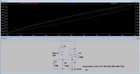
As you can see close to the max. dissipation (5W) cathode current (anode current+grid current) is (about) 70mA, but grid current also too high (8mA).
Voltage drop depends on the anode current, almost linear between 27 and 54V.
Attachments
Last edited:
Using a GZ34, I am measuring 640VAC in the input side (320 plate to center tap) and 290VDC right after the rectifier and before the first filter cap. I know the data sheet says 17V dropped per plate, but I assumed that this meant (320 * 1.414) - 17, but am I wrong? If I want at least 370VDC before the first filter cap, do I need a 400-0-400 transformer? Duncan amps tool gives me totally different results.
http://www.r-type.org/pdfs/gz34.pdf
page 6, 17v at 270ma?
i would think same way.
1,414 cap input
0,9 choke input
- Status
- This old topic is closed. If you want to reopen this topic, contact a moderator using the "Report Post" button.
- Home
- Amplifiers
- Power Supplies
- rectifier voltage drop