My current high-power off-line SMPS work requires big toroid transformers and variacs to be employed in order to achieve proper mains isolation and voltage adjustment. That is currently involving three 1KVA toroids, another 750VA one, a smaller 470VA one, and a 5KA variac is hopefully coming next week. Furthermore, the AC output of the transformers has to be usually rectified and fed to high value capacitors in order to fed the SMPS test circuits with reasonably steady DC.
Well, after blowing two 35A diode bridges and another 50A one in a week and tripping circuit breakers several dozen times, I got really fed up this morning and figured out a simple soft-start circuit.
The triac shunts the 10 ohm ballast resistor as soon as the ~13V undervoltage lockout (leftmost comparator) allows the trigger oscillator to run (rightmost comparator). That takes approx 70ms to happen (it depends on mains voltage), which is just enough time to tame the initial inrush current transient.
Since 50mA of gate current are required in order to guarantee proper triggering of my BTA16-600B triac, a 10Khz oscillator is employed, which feeds the gate with 5us 50mA pulses every 100us. Trigger quadrants are I and III. As a result circuit current consumption is reduced to approx. 3.75mA, being 2.5mA (average) employed to trigger the triac and 1.25mA used by the rest of the stuff. The led came for free.
Due to the very low supply current requirements, the circuit is easily powered from the mains line through a ballast capacitor as shown in the schematic. After the first tests everything seems to work just fine.
Enjoy...
Obvious disclaimer: Working with mains live circuits is dangerous and can result in fire, injuries, death, etc... So if you decide to use the information contained in this post you must do it at your very own risk.
Well, after blowing two 35A diode bridges and another 50A one in a week and tripping circuit breakers several dozen times, I got really fed up this morning and figured out a simple soft-start circuit.
An externally hosted image should be here but it was not working when we last tested it.
The triac shunts the 10 ohm ballast resistor as soon as the ~13V undervoltage lockout (leftmost comparator) allows the trigger oscillator to run (rightmost comparator). That takes approx 70ms to happen (it depends on mains voltage), which is just enough time to tame the initial inrush current transient.
Since 50mA of gate current are required in order to guarantee proper triggering of my BTA16-600B triac, a 10Khz oscillator is employed, which feeds the gate with 5us 50mA pulses every 100us. Trigger quadrants are I and III. As a result circuit current consumption is reduced to approx. 3.75mA, being 2.5mA (average) employed to trigger the triac and 1.25mA used by the rest of the stuff. The led came for free.
Due to the very low supply current requirements, the circuit is easily powered from the mains line through a ballast capacitor as shown in the schematic. After the first tests everything seems to work just fine.
Enjoy...
Obvious disclaimer: Working with mains live circuits is dangerous and can result in fire, injuries, death, etc... So if you decide to use the information contained in this post you must do it at your very own risk.
One thing is missing for safety. In case of catastrophic failure of the control circuit, always a risk when running directly from main voltage, the power resistor can become dangerously hot and burn. A risk of fire is even present. Elliott, on is web site (http://sound.westhost.com/project39.htm) has an excellent discussion on the subject.
I would recommend as a safety to install a thermal fuse in serie with the power resistor. This fuse is mounted side by side with the power resistor and coupled using a metal bracket or clip. This way if the circuit fails, the power resistor will heat and trig the fuse that will kill the power and protect the equipment.
Just my two cents")
I would recommend as a safety to install a thermal fuse in serie with the power resistor. This fuse is mounted side by side with the power resistor and coupled using a metal bracket or clip. This way if the circuit fails, the power resistor will heat and trig the fuse that will kill the power and protect the equipment.
Just my two cents
Oh, but every traditional relay-based circuit has the very same pitfall.
Actually I have an unfinished version of that circuit that does not use a ballast resistor and is based in a trigger phase sweep, but it's controlled by a PIC12C508 and the code is not finished yet. I was in a hurry and needed something that I could get working in a couple hours.
Actually I have an unfinished version of that circuit that does not use a ballast resistor and is based in a trigger phase sweep, but it's controlled by a PIC12C508 and the code is not finished yet. I was in a hurry and needed something that I could get working in a couple hours.
Nice circuit. But I might have found something to whine about.
If the circuit is switched on when the mains is at its peak, the 1N4148 would have to pass 3 amperes for a brief moment. Isn't that a bit close to its peak rating? (1 amp for 1ms, 4 amps for 1us). 1N4001s aren't that much more expensive are they? The 100 ohm resistor should be rated to take the full voltage too I guess.
Must seem like I have no life, pointing out something like this
But I might have found something to whine about. If the circuit is switched on when the mains is at its peak, the 1N4148 would have to pass 3 amperes for a brief moment. Isn't that a bit close to its peak rating? (1 amp for 1ms, 4 amps for 1us). 1N4001s aren't that much more expensive are they?
The 100 ohm resistor should be rated to take the full voltage too I guess.Must seem like I have no life, pointing out something like this
Hi,
nice one!
any info on selecting triac parameters? (just in case we have to buy something different and have a lower load)
and I'll claim the author's fee three times over.I'd send it to AudioXpress, EDN or Elektor --
nice one!
any info on selecting triac parameters? (just in case we have to buy something different and have a lower load)
luka said:Looks great, maybe some sort of fuse would be a good thing to have before whole circuit to stop its functions just in case something does go horribly wrong.
Nice work...
I thought that it was too obvious to mention... Yes, it does require a fuse, and indeed there are a couple of them, and more...
An externally hosted image should be here but it was not working when we last tested it.
Hi Eva,
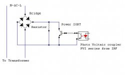
Here is my idea....simple version using IGBT as a switch and Driving it from PVI coupler, just an idea...only
for PVI have a look at this
http://www.irf.com/product-info/datasheets/data/pvin.pdf
The LED Trigger circuit could made easily with few passive components for working from mains directly
K a n w a r
Attachments
Regarding the balast resistor getting hot, a method i used with Rod Elliott's soft start was to squeeze a small thermal link in between two of the stacked power resistors. Since I build nearly all my amps with a "slave" relay triggered by 12V DC from a preamp, I just connect the thermal link in series with the 12V trigger. This could be applied to any soft start with a balast resistor.
I was tempted to use a thermal switch, but that promotes laziness/ The fusible link forces me to open the unit and figure out what went wrong.
I was tempted to use a thermal switch, but that promotes laziness/ The fusible link forces me to open the unit and figure out what went wrong.
Really nice circuit there Eva. 
Hm, why dont we take the ballast resistor out at all ?
I've been tinkering phase angle controlled soft start, I'll post the schematics as soon as I sort out how to trigger the triac correctly.
Main idea is that window comparator tied through a cap to the mains allows us to generate zero transition pulses, they control the current source which generates a nice inverse ramp and comparing that with a slowly rising reference slowly increases power in the load, at the end we just supply some current into the triac to make sure its always conducting.
The circiut will use 3 comparators of LM339, 3 transistors(BC8xx or BC5xx) and bunch of resistors and a triac, so it will be cheap and if it fails it either doesnt work or it pretends its not there if shorted.
The only advantage is that relay doenst waste much power, well except for coil.
Hi Folks,
Here is an Atmel IC for softstart using Triac ...
See this link
http://www.atmel.com/dyn/resources/prod_documents/doc4766.pdf
K a n w a r
Here is an Atmel IC for softstart using Triac ...
See this link
http://www.atmel.com/dyn/resources/prod_documents/doc4766.pdf
K a n w a r
There is no question that Triac based soft starts can and do work. The big question is: Do they work silently?? I would be interested to hear (no pun) from Eva on this.
To date my experience is that a triac in series with a big inductor, i.e., power transformer, is not silent. I'm not talking just electrical noise that reaches an amplifier output but especially a buzz that is audible when idle. The best I've come across is that the noice is pretty much contained by the enclosure and not appearent when you stand back a few feet. Being on the same circuit as a light dimmer or in a household with multiple SMPS's (i.e., PCs) just makes inaudibility harder to atain.
For me I'll take a single relay click over continuous hum any day.
sam9 said:There is no question that Triac based soft starts can and do work. The big question is: Do they work silently?? I would be interested to hear (no pun) from Eva on this.
To date my experience is that a triac in series with a big inductor, i.e., power transformer, is not silent. I'm not talking just electrical noise that reaches an amplifier output but especially a buzz that is audible when idle. The best I've come across is that the noice is pretty much contained by the enclosure and not appearent when you stand back a few feet. Being on the same circuit as a light dimmer or in a household with multiple SMPS's (i.e., PCs) just makes inaudibility harder to atain.
For me I'll take a single relay click over continuous hum any day.
There is no added noise at all (electrical or acoustic) because the 10Khz oscillator guarantees that the triac is kept continuously triggered (I have just checked with oscilloscope), remember that triacs are very slow devices that take a lot of time to unlatch and turn off. Furthermore, I have just tried adding a gentle DC offset to the mains line with the help of an old 1500W electric heater that achieves half power setting with a diode in series, and the circuit is clearly showing some mild DC blocking action because the transformers become noisier if I short the triac directly across its legs with a screwdriver (quick dirty test indeed).
megajocke said:Nice circuit.
If the circuit is switched on when the mains is at its peak, the 1N4148 would have to pass 3 amperes for a brief moment. Isn't that a bit close to its peak rating? (1 amp for 1ms, 4 amps for 1us). 1N4001s aren't that much more expensive are they?
Must seem like I have no life, pointing out something like this
Indeed a 1N400x is much better there.
mitwrong said:HI,
The cct design is great, but no feed back element like opti- coupler, the AC input with no protection like fuse, surge diode and filter coil that prevents EMI interference.


____________________
WE APPRICIATED SAFETY
This circuit causes no EMI because the triac is kept continuously on. The other elements mentioned should be already present in the existing circuit to which the soft-start feature is added...
Workhorse said:Hi Eva,
Here is my idea....simple version using IGBT as a switch and Driving it from PVI coupler, just an idea...only
for PVI have a look at this
http://www.irf.com/product-info/datasheets/data/pvin.pdf
The LED Trigger circuit could made easily with few passive components for working from mains directly
K a n w a r
Then you end up with 2V @20A drop from the diode bridge plus another 1.5V @20A from the IGBT (assuming a standard speed one is chosen). Compare that to the 1.5V @20A from the triac, which has no rival when it comes to solid state switching of AC mains. If you want optocoupler triggering, consider a MOC3020 optotriac, and note that it does not require an additional power supply.
VEC7OR said:Really nice circuit there Eva.
Hm, why dont we take the ballast resistor out at all ?
I've been tinkering phase angle controlled soft start, I'll post the schematics as soon as I sort out how to trigger the triac correctly.
Main idea is that window comparator tied through a cap to the mains allows us to generate zero transition pulses, they control the current source which generates a nice inverse ramp and comparing that with a slowly rising reference slowly increases power in the load, at the end we just supply some current into the triac to make sure its always conducting.
The circiut will use 3 comparators of LM339, 3 transistors(BC8xx or BC5xx) and bunch of resistors and a triac, so it will be cheap and if it fails it either doesnt work or it pretends its not there if shorted.
The only advantage is that relay doenst waste much power, well except for coil.
I tried it that way some time ago, and it worked fine, but I ended up with a too high part count for a dumb soft start circuit, so I dumped the idea in favour of a PIC12C508, which could also allow to implement more features in software like on-off pushbutton, latching shutdown, brownout detection, etc.. without adding more parts.
Workhorse said:Hi Folks,
Here is an Atmel IC for softstart using Triac ...
See this link
http://www.atmel.com/dyn/resources/prod_documents/doc4766.pdf
K a n w a r
Great but it seems expensive and very hard to get. Compare it to the standard parts employed in my circuit or to those 8-pin low-cost PICs available in every store (with dozens of webs showing free programmer plans and code).
AndrewT said:Hi, and I'll claim the author's fee three times over.
nice one!
any info on selecting triac parameters? (just in case we have to buy something different and have a lower load)
Thanks
Any standard sensitivity triac (Igt=50mA) rated at enough voltage and current is enough, with no extra features like "snubberless", "three-quadrant" or "sensitive-gate". Note that my triac is inexpensive and not particularly big for my setup, since it comes in a TO-220 case and it's rated at 16A, but it was what I had in my parts box...
Nice circuit! Thanks for share…
I have the some problem.
Some time ago I found this one:
http://www.bryston.ca/BrystonSite05/pdfs/SSTAmplifiers/9Bsst-Schematic12(2002-07,2004-06).pdf
See page 4/5
The circuit is an AC Dimmer and I have made it with 2 big thiristors and diodes with my own discrete controller version.
In my case, the dimmer attacks directly the smps input capacitors...12x2200uF-200V (series/parallel arrangement)
The thiristors and diodes are in fact the input bridge rectifier.
Modifying the bridge structure the dimmer could soft start big toroids without problem, slowly charging the capacitors with growing “dimmered” peak voltage.
One collateral advantage is the possibility of switch the full smps with a small switch or a remote signal…like protection circuitry.
If some one teaches me the way of post big pictures like the EVA ones, I could post the PARTIAL schematic…
- Status
- This old topic is closed. If you want to reopen this topic, contact a moderator using the "Report Post" button.
- Home
- Amplifiers
- Power Supplies
- Soft-start circuit with no relays and no aux. transformers