Hi everyone, I've decided to biuld an offline SMPS.
It will have around ~500-600W of power (in the top range for the half-bridge designs). Any comments on the topology of the circiut ?
I have couple of questions about:
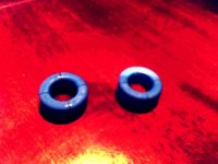
1) current transformer, what magnetic material is better to use for it ?
2) I've read alot of scary stories about flux imbalance/walking during regulation of the PSU, how bad is it with half-bridge design ? I'll have cycle by cycle current limiting implemented, so I think it wont be a problem, if core will go into saturation it should be corrected through current limiter, right ?
3) Do I require any freewheeling diodes for this design (apart those in FETs, but they are slow and stuff)?
FETs most likely will be IRF740 or similar, switching frequency around 75kHz.
Controller and driver are LM5030 and IR2110. I chose those because they are easy and relatively cheap to get plus I think I understand how LM5030 works good enough to try it. (Yeah, I also plan using it for car SMPS, but thats another story)
It will have around ~500-600W of power (in the top range for the half-bridge designs). Any comments on the topology of the circiut ?
I have couple of questions about:
1) current transformer, what magnetic material is better to use for it ?
2) I've read alot of scary stories about flux imbalance/walking during regulation of the PSU, how bad is it with half-bridge design ? I'll have cycle by cycle current limiting implemented, so I think it wont be a problem, if core will go into saturation it should be corrected through current limiter, right ?
3) Do I require any freewheeling diodes for this design (apart those in FETs, but they are slow and stuff)?
FETs most likely will be IRF740 or similar, switching frequency around 75kHz.
Controller and driver are LM5030 and IR2110. I chose those because they are easy and relatively cheap to get plus I think I understand how LM5030 works good enough to try it. (Yeah, I also plan using it for car SMPS, but thats another story)
Attachments
Hi. If you place something like a 1uF film capacitor in series with the transformer primary, that should remove concern about transformer saturation. You could change things a little more, even. Use one bulk filter capacitor. But then use two film capacitors in series across the big electrolytic one. Connect the transformer primary to the midpoint between the film capacitors.
I would also add a mutually coupled inductor right after the output diode bridge before the filter caps.
Have you considered PFC? Since you're not making this 115-230V switchable, very high voltage (>300V) won't be a concern. This would lower, dramatically, the peak currents that would be going through the input diode bridge.
Othar than that, It looks good. Coilcraft makes some off-the-shelf current sensing transformers that are good for 50-200kHz.
Steve
subwo1 said:Hi. If you place something like a 1uF film capacitor in series with the transformer primary, that should remove concern about transformer saturation. You could change things a little more, even. Use one bulk filter capacitor. But then use two film capacitors in series across the big electrolytic one. Connect the transformer primary to the midpoint between the film capacitors.
I've been thinking about it, but what about staircase saturation ? Another thing that how big those caps would be ? Hm, the frequency is rather high, so something in ~1-2.2uF would do.
N-Channel said:I would also add a mutually coupled inductor right after the output diode bridge before the filter caps.
Have you considered PFC? Since you're not making this 115-230V switchable, very high voltage (>300V) won't be a concern. This would lower, dramatically, the peak currents that would be going through the input diode bridge.
Othar than that, It looks good. Coilcraft makes some off-the-shelf current sensing transformers that are good for 50-200kHz.
Steve
Hm, PFC, yeah, up to a point, but this adds complexity and reduces efficiency a bit, and what PFC method would you recommend ? In that case I would choose boost converter based PFC with continous conduction mode, using IR1150, so far its the best solution I've seen, least component count, easy to implement, very high power possible. Another thing that PFC at 500-600W requires a hefty inductor.
I've also thought about adding a mutually coupled inductor, for that very purpose I have some slotted toroids (Epcos, N27 material), these just dont saturate
")
Thanks for pointing out on Coilcraft, its a pity no local distributor carries their products, but i think I'll order from them directly.
Attachments
I'd say that to lessen the ability of the transformer to saturate that way or in any other is one advantage of using the coupling capacitor or capacitors. It is even possible to use much smaller of this primary coupling capacitance than normal. Then you would need a couple of high speed diodes to shunt resonance peaks to the power supply rails. You lose a little efficiency, but the primary circuit may gain simplicity and some extra current limiting if you can do away with the current mode control. During overload then, the circuit will move toward switching at zero primary current, depending on the voltage on the secondary side.
Vec,
For your mutually-coupled Inductor, I would grab the BIG yellow toroid out of an old PC supply, and re-wind it for your application. These NEVER saturate, and they are cheap and readily available, usually for a song.
Yes, I would also stick with continuous-conduction mode boost converter for the PFC, because it is the preferred method for power levels over ~300W.
Unitrode's UC3854 is a good candidate because it operates constant-frequency, and can be synch'ed with the PWM.
Steve
N-Channel said:Vec,
For your mutually-coupled Inductor, I would grab the BIG yellow toroid out of an old PC supply, and re-wind it for your application. These NEVER saturate, and they are cheap and readily available, usually for a song.
Yes, I would also stick with continuous-conduction mode boost converter for the PFC, because it is the preferred method for power levels over ~300W.
Unitrode's UC3854 is a good candidate because it operates constant-frequency, and can be synch'ed with the PWM.
Steve
I know that those are good, but I got these toroids from a dude who designs SMPS's for like 30 years, he said that he tried numerous ways to overcome losses and saturation, used many types of materials and says that this is the best he came up with.
I think I'll skip the PFC this time, moreover in my country, we dont pay for reactive power and PFC isn't a requirement, YET.
Here is the second version of the psu, now the trasformer is connected to smaller capacitors and electrolytics are on rails.
I've been thinking about using a toroid for this project, but for offline we need better isolation, so I plan to order some EDT cores from Distrelec, EDT44 - EDT59 range, or should I better stick with toroids ?
P.S. I can attach the bigger schematics if anyone is interested.
Attachments
Subwo: I wonder why? I'm suffering from Avatar-envy.
VEC: Just an idea, I would place the first set of 470mF caps on the secondary side AFTER the 20 mH inductors. I looked at the datasheet for the LM5030. Slick little chip.... Since PFC is not in the cards for now, that's fine, but I would rate everything on the primary side for 500V nonetheless, so when (and if) you decide (or have to) PFC the front end, you won't have to change a whole lot, just the primary windings.
Oh, I vote for the Totoids, too.
I'm suffering from Avatar-envy. VEC: Just an idea, I would place the first set of 470mF caps on the secondary side AFTER the 20 mH inductors. I looked at the datasheet for the LM5030. Slick little chip....
Since PFC is not in the cards for now, that's fine, but I would rate everything on the primary side for 500V nonetheless, so when (and if) you decide (or have to) PFC the front end, you won't have to change a whole lot, just the primary windings.Oh, I vote for the Totoids, too.
N-Channel said:Subwo: I wonder why?
VEC: Just an idea, I would place the first set of 470mF caps on the secondary side AFTER the 20 mH inductors. I looked at the datasheet for the LM5030. Slick little chip....
Oh, I vote for the Totoids, too.
I also thought about the secondary caps to be moved after the inductor. BTW I found that chip here, at DIYaudio, I've been looking for a decent chip for a push-pull converter, and after a while I saw that it will make a nice controller for offline PSU provided with a HV driver.
Rate everything for 500V ? It could be done, but I dont see any nice FETs around for that, but it sure could be done, later, replace the caps, replace the fets, presto!
BTW The startup circuit need to be redone, internal regulator of the controller chip will supply ~7V, enough to open the fets, but isnt enough to start the driver (it has a lockout at 8.5V), so maybe I'll just stick another resistor from upper rail to Vcc pin, to charge the cap and implement some kind of inhibit, which pulls SS pin to ground for a moment until Vcc reaches ~9-12V.
I'm aware of those, but they are slower than IRF740 and cost twice as much (~1 buck for 740 and ~2.3 for 460), anyway if feel like it I'll probably sell the PSU and make another one, moreover its perfectly siuted for a bunch of 70-80W amps and there are alot of LM3886 junkies around who will take it.
Re: reply
Hi rejithcv,
2sk2996 is not available here.
Current transformer is generally made out of the same material that of the main transformer, just smaller in size, only thing to look out for - make sure that the core you are using can handle the current you plan to measure without climbing to saturation, the rest is done throught termination resistance, etc.
Done third revision of the converter, now it has a startup regulator based on MPSA44, and startup inhibit for the time until the supply reaches atleast 9.6V, when aux winding takes over it is effectively turned off. Time to go through the controll loop and the magnetics.
rejithcv said:Try 2sk2996 (600v ,0.74 ohm) . It seems to be cheap. Good luck!
hi vec,
How u made the CT (material & winding)?
Hi rejithcv,
2sk2996 is not available here.
Current transformer is generally made out of the same material that of the main transformer, just smaller in size, only thing to look out for - make sure that the core you are using can handle the current you plan to measure without climbing to saturation, the rest is done throught termination resistance, etc.
Done third revision of the converter, now it has a startup regulator based on MPSA44, and startup inhibit for the time until the supply reaches atleast 9.6V, when aux winding takes over it is effectively turned off. Time to go through the controll loop and the magnetics.
Attachments
VEC7OR ,
One of the issues with SMPS is that they appear to be deceptively simple. However, the are not at all simple. There are quite a few problems in your circuit. Here are some of them, but this is not an exhaustive list.
1. Since this is a current mode circuit, you need to add provisions to prevent a volt second imbalance in the power transformer. The is an old Unitrode application note on a half bridge power supply that may be helpful.
http://focus.ti.com/lit/ml/slup083/slup083.pdf
2. I know that this is a work in process, but you will need to add snubbers, probably around the output of the transformer or the diodes.
3. The 1uF bus bias caps are too small.
4. The MPSA44 will be overstressed during turn on.
5. I know you haven't picked the FETs, but 33 ohms in the gate circuit seems too large.
6. D5 needs to be a fast diode.
7. Q5 will never turn on, if the output of your startup supply is only 9.3 volts.
I haven't looked at the details of the gate drive or control circuit.
Please understand that I have brought these issues to your attention, only to make you aware of them; I do not intend to be negative or critical.
Rick
- Status
- This old topic is closed. If you want to reopen this topic, contact a moderator using the "Report Post" button.
- Home
- Amplifiers
- Power Supplies
- Offline ~500W SMPS