hi all!
i know it is quite impossible that nobody thought about it, but i can't find any topic talking about it...
my question is: is it possilbe to wire in series two or more smps power supplies?i mean like the PC power supply?maybe with some extra circuitry...
And is it possible to obtain a negative voltage from them?maybe to have a splitted power supply...i don't have much experience with smps, maybe someone can help...
thanx in advance!!
Expanding on Jimbo's  answer here, you could replace the two 1A diodes on the -12V line with an MUR1620CTR, which is essentially the negative version of the common-anode dual rectifier that powers the +12V line. Decoding its part number reveals it to be a Motorola Ultrafast Rectifier, 16A (8A per leg), 200PIV, Center-Tap, Reverse dual diode.
This would get you a -12V of several amperes, but you would still need to adequately filter it like its complimentary +12V side.
Steve
answer here, you could replace the two 1A diodes on the -12V line with an MUR1620CTR, which is essentially the negative version of the common-anode dual rectifier that powers the +12V line. Decoding its part number reveals it to be a Motorola Ultrafast Rectifier, 16A (8A per leg), 200PIV, Center-Tap, Reverse dual diode.This would get you a -12V of several amperes, but you would still need to adequately filter it like its complimentary +12V side.
Steve
ok...my idea was to use just the +12V that is capable to source 30 or more amps, and wire more power supplies in series to obtain for example +/-24V@30A, a reasonable power!and this link could help:
http://myweb.tiscali.co.uk/nuukspot/decdun/gainclonesmps.html
he says that you just need to isolate the output, as already said...anyone tried to do it?
http://myweb.tiscali.co.uk/nuukspot/decdun/gainclonesmps.html
he says that you just need to isolate the output, as already said...anyone tried to do it?
You can do that provided that the outputs of the supplies are isolated and that both of them are equal (or at least both of them are rated at least at the current you are demanding).
I have notices that some of our customers have used our coldamp SPS80 supplies in series to obtain HV voltages required for tubes.
I have notices that some of our customers have used our coldamp SPS80 supplies in series to obtain HV voltages required for tubes.
Word of caution: Most pc supplies' 12V sections are rated for only about 8-10 Amps, so you would have to parallel as well as series several units to get the +/-24V@30A. BTW, this is 1.5kW. At that point, it might be more cost-effective to just fabricate your own, using parts and ideas from the original circuit.
Using a pair of PC power supplies for generating split DC voltage rails IS NOT ADVISED.
1) Most PC supplies are built with the absolute cheapest parts available, which should obviate their use in any audio system, even a poor quality one.
2) The effort and expense required will be too great, the costs of isolating the cases, power feeds, etc. to insure decent results without buring down your house = :>( . (It would be cheaper and produce better results to get a couple of auto batteries and a couple of trickle chargers = +/- 12 to 13.5 VDC rails.)
3) Even if your succeed, you will have to constantly trim the regulators to get balance between the rails ... PC supplies drift over a range of greater than 3% ... and one may be drifting up while the other is drifting down = error greater than 6%.
...
If you insist on using PC power supplies for something, save the case, save the power cord, connection & power switch(s) and install your own transformer and bridge / cap module ... or (if you must) get an audio quality, switching power supply board that fits inside the PC PS case.
The problem with your suggestion is that PC switching supplies are preceived to be quite powerful, but at a low voltage. In reality the PC power supply makers lie: their power ratings are never rated "continuous" ... and the mis-conception is that "stacking" them in series is "additive" = NOT!. Besides the PC PS pecularity of being in about exactly the wrong frequency for audio work, their truely "anemic" nature, poor quality and lack of decent isolation will result in very ugly, noisey power ... if you don't manage to start a fire.
There are linear, +/- 12 VDC and +/- 24 VDC power supply kits that will fit inside a PC PS case, However, from your suggestions above (+/- 24 VDC @ 30 amps =~~ 750 watts) this will be a neat trick, but it could be done.
...
thanx to all guys...")
and what about obtaining 17V simply by using the 12 and 5V?i've seen the atx schematic, using +12 and +5 is impossible because they are tied on the secondary, +12 and -5v can be done disconnecting the gnd...but the -5 is rated 0.5A, should i change the diodes and raise the current capability?
and what about obtaining 17V simply by using the 12 and 5V?i've seen the atx schematic, using +12 and +5 is impossible because they are tied on the secondary, +12 and -5v can be done disconnecting the gnd...but the -5 is rated 0.5A, should i change the diodes and raise the current capability?
" ... what about obtaining 17V simply by using the 12 and 5V? ..."
Previous: " ... besides the PC PS pecularity of being in about exactly the wrong frequency for audio work, their truely "anemic" nature, poor quality and lack of decent isolation will result in very ugly, noisey power ..."
A complete redesign would be required to get audio quality results = more money and time than starting from scratch (whether using the case and power parts or not).
I would like to add a little balance to this thread, being I am one of experience with using computer SMPS series setups.
You cannot base the possible audio or other outcomes on what people have said here until you have tried it; after all, this is the true essence of 'do it yourself.'
If you want to put computer SMPS supples in series, you must be careful about it, but it is not difficult by any stretch of the idea.
You must unground at least one of the supplies in order to run them in series since the zero volt (black) rail on any supply is normally connected to ground internally. If you're into re-designing things like I am, you can isolate the internals of the supply from the primary, but this 'is' difficult and I don't recommend it as a simple project.
The easiest way to run in series is to simply unground one supply and leave the other with a ground. There are safety issues with this as the MOV(metal oxide varistors) in the supply need ground in order to work, so this is not considered essentially that safe but can be done at your own risk.
As far as the operation of the supplies in series, don't worry about what others have said about voltage drift over time. A computer supply has little real problem with that and you must remember that an un-regulated linear supply can and always does experience great voltage drift because of the varying quality of your power from the wall. This is normal and most good amplifier designs should be fine with this. A series SMPS setup will offer still better stability than any un-regulated linear anyway. (My amplifier design uses a linear supply as mentioned and has a voltage meter on the panel to indicate my rail voltage, this fluctuates surprisingly with the power demand in the neighborhood.) I'll add that my amplifier, even though designed to operate nominally with 85V +/- (170V) will operate with negligeable change down to 1.5V +/-, thus you can see that regulation is not an issue clipping level aside.
Just be careful and logical about the fact that the computer supplies are ground referenced and wire accordingly, they are well protected and so shouldn't fry too badly if you do something wrong, just be careful on the input side that you have things done correctly and do this with fuses in place to prevent catastrophy.
Any questions for me, just ask or send a private message.
" ... Just be careful and logical about the fact that the computer supplies are ground referenced and wire accordingly, they are well protected and so shouldn't fry too badly if you do something wrong, just be careful on the input side that you have things done correctly and do this with fuses in place to prevent catastrophy. ..."
Yes, it appears to be quite a neat trick.
The only thing I might wonder about is what happens in use ... Is the noise removed or bothersome? ... Is there any serious concerns about the "ungrounded" v. "grounded" supplies going out of balance ( Ex: +5 VDC verses - 5 VDC having wild swings +/- more than a few %) ??
We all knew that it could be done, just concerned that if done it would be worthwhile and safe to use??
Well, going on both theory and experience, this method of using SMPS units in series is no real problem.
In use, my series SMPS setups have shown no unusual effects to the end of rugelation or noise. They perform better than their linear counterpart with the exception of simplicity and probably in the extreme long run, reliability.
My recommendation to anyone interested in trying this is to try it as long as you understand how the power supplies are connected to the mains and are grounded. You must wire accordingly as I have said.
If you want the best case scenario, you could take the next step as I have done: I re-designed a SMPS completely by rewinding the transformer and replacing all of the rectification, filter, and feedback circuitry with my own. My result: A split 50V (25V +/-) supply with excellent balance and clean output.
Such heavy modification is, of course, not for the light hearted.
raikkonen said:thanx to all guys...
and what about obtaining 17V simply by using the 12 and 5V?i've seen the atx schematic, using +12 and +5 is impossible because they are tied on the secondary, +12 and -5v can be done disconnecting the gnd...but the -5 is rated 0.5A, should i change the diodes and raise the current capability?
Yes, you could change the two 1A diodes feeding the -5V line with a couple of high-current Schottkys, like say, MBR1645 (16A, 45 PIV). These should be drop-in replacements, but if you want to use a single diode package, try the MUR1620CT-R (see post #4, this thread).
But, why 17V? Why not 24V (+/- 12V lines)? This way, you can get the (+) and (-) voltages you want, without having to use a second supply. Just a thought............
You could always re-wind the transformer to put out the +/-24V you were originally seeking, and change the output caps and sense resistors to compensate for the higher voltage(s).
By having all power supplied by one unit, you will eliminate the possibility of "beat" frequencies from being generated from two PWMs in close proximity, running at nearly the same (but not exact) frequency.
well, the 17V comes from the fact that i've got some speakers, some ATX and some chip amps on my desk...and i have to match them in some way to obtain a little nice system!TDA series for car uses a max supply of 18V so...
thanx N-channell, i think the idea of the diodes is very good and easy...re-wiring the coils is quite too much for me...
and what about using + and -12 to obtain 24V and then using a linear regulator to have 18V regulated and filtered?is it a stupid idea?
thanx N-channell, i think the idea of the diodes is very good and easy...re-wiring the coils is quite too much for me...
and what about using + and -12 to obtain 24V and then using a linear regulator to have 18V regulated and filtered?is it a stupid idea?
Here is a reperesentative ATX schematic. The resistor Eva refers to is the one next to the word "Feedback", valued at 27K. I can't make out its designation, but I think it says "Rfb". Change this to a higher value, or even better yet, put a 10K pot in series with it, and adjust it up to the desired +17V.
As there are literally hundreds of AT & ATX schematics, this is a representation ONLY. (Your mileage may vary. )
Of course, this is predicated on the notion that you have changed C20, the 1000uF cap to a 25V unit, FIRST.
Steve
As there are literally hundreds of AT & ATX schematics, this is a representation ONLY. (Your mileage may vary.
) Of course, this is predicated on the notion that you have changed C20, the 1000uF cap to a 25V unit, FIRST.
Steve
Attachments
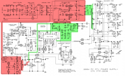
There is actually more stuff to change, since the voltage of the rest of the outputs will increase proportionally too. There are two ways to handle that, either to remove all the components associated to the other outputs, or to modify the +5V feedback resistor, the overvoltage protection networks and check that all the capacitors can handle the increased voltage. The former is usually the easier solution.
- Status
- This old topic is closed. If you want to reopen this topic, contact a moderator using the "Report Post" button.
- Home
- Amplifiers
- Power Supplies
- wiring smps in series