I have constructed a simple testbed consisting of a signal generator (square wave) and my oscilloscope to test ESR and step response of parallell capacitor combinations. What I have observed annoys me, no matter how yucky and old high-ESR electrolytes I parallell 100nF X7R with, I get horrid ringing (less ringing the worse the ESR of the electrolyte, but still too much).
Based on this, what is the general recommendation to use to get low and ringing-free ESR across a broad frequency range? How much ringing is normally accepted for decoupling of say zener followers subjected to really noisy power and subjected to step-formed load? (something like 100uF base, that keeps its ESR up in the 30+ MHz range)
/Daniel
That's really a hard to answer question. There may be some problem with your test setup because at least some capacitor combinations should not ring at all when connections are short enough. Anyway, I usually check for ringing in the application PCB (with whatever internal excitation exists) in a circuit by circuit basis rather than in a separate test setup.
Hi zilog
In my opinion, the ringing you observe is generated by your test set-up, and not specifically by the capacitors under test; the Q of the tank circuits formed by the parasitics will normally be very low and could hardly produce a sustained ringing (unless you're looking for troubles by leaving 1 inch wires at the ends of each components).
I've just made a small test in the lab to confirm this: I hooked a 20V pp square wave generator running at 10KHz to an injection resistor of 330R connected to the CUT, a 15 y.o. 47µ/16V. The oscilloscope probe was connected directly across the CUT.
As expected, the waveform was a mix of triangle (caused by the capacitive part of the impedance) and square, caused by the ESR.
In addition, at each switching edge, a short, nasty transient having ~2 times the amplitude of the waveform was also visible.
By short circuiting the capacitor, I could totally remove the base waveform, but the transient was barely affected. I went further and removed completely the oscilloscope probe. I short-circuited the tip with the 2 inch grounding wire, and touched the cold side of the CUT with the grounded tip, and banco! the transient was back.
Yet my set-up was nice and clean, with signal and return wires following the same paths, etc
This simply shows you've to be extra careful, put common mode chokes or ferrites on each cable, very close to the CUT, avoid any common loops, etc etc.
I'd advise you to replace your CUT's with a portion of wire and you work your test configuration until you're satisfied it's completely clean.
LV
Interesting stuff indeed. What is apparent from these curves is that the addition of a smaller capacitor in // with an electrolytic adds a dip in the impedance at some resonance frequency; this dip however doesn't mean there will be any ringing at this frequency, quite the opposite in fact: this behaviour is typical of a series resonant circuit, and to get ringing you need a parallel circuit.powerbecker said:
With longer wires, the overall impedance is somewhat raised around the resonance, but the Q is too low to call it a parallel resonance.
By using a combination of a good electrolytic, long wires and a relatively low value film, in the 10nF range, you could build a resonant circuit having a significant Q at several MHz. With a loop inductance of 100nH f.e., the resonance would occur at 5MHz.
Some advocate this type of combination of a very low value non-polarized cap in // with the electrolytic, but this is clearly not a good idea.
At audio frequencies, all this is mainly irrelevant, but for class D amplifiers, it could be much more important.
LV
Hi Ziloq and Elvee
I am finding your results and comments very interesting.
I am currently seaching for the "best Capacitor arrangement" to use on the output of a preamp to filter out dc. I have two similar preamps; one with no some dc across the output and one with some dc ( which I will later remove by component matching ).
However I decided to play around with various types and sizes of capacitor to listen for myself if there was any significant difference btween difference values and types of capacitor. The value is in the 2.5uf to 10uf range and is being used in the positive output with a resistor across the positive and negative outputs to form a filter.
The general feeling of most being that a polypropylene capacitor is "normally" the best sounding. I have been testing for some weeks.
What I have found is;
1) Polypropylene and polycarbonate do sound best to me.
2) They seem to sound better with a polystyrene capacitor in parallel. 0.047 uf sounded best. This improved the treble.
3) They seemed to sound better with a larger value polycarbonate capacitor also paralled with them. ( The base became firmer ). The best seemed to be 10uf - but that may be related to my system and the filter resistor value.
4) I could not find any electrolytic capacitors that sounded better than the above - and I own a few well thought of types.
I do not own any analysis equipment so I found your comment above of great interest.
From the listening that I undertook I am in little doubt that parrelling capacitors sounds better to me. I found the best ;
-10uh polycarbonate
-1uf polypropylene
- 0.047uf polystyrene
Can the scientific approach that you are adopting come to any pointers that could help to parallel capacitors with more certainty?
Don
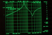
To illustrate what I said in my previous post, I've made a VNA measurement on a combination of a 220µ/10v Oscon cap paralleled with a 10nF polypropylene film cap.
The measurement point is right at the 10nF pins, and the wires to the 220µ are exactly 50mm long.
You can see a strong parallel resonance at just below 6MHz, followed by a series resonance at over 20MHz.
The attenuation at 6MHz is only 3dB (it's a 75R system)
The measurement point is right at the 10nF pins, and the wires to the 220µ are exactly 50mm long.
You can see a strong parallel resonance at just below 6MHz, followed by a series resonance at over 20MHz.
The attenuation at 6MHz is only 3dB (it's a 75R system)
Attachments
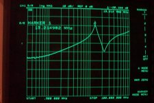
For reference, here is the same measurement taken without the 50mm wires (both caps directly in parallel).
The parallel peak is now at 13MHz and 20dB below the reference, and it shoots only moderately over the normal, inductive slope of the curve.
The parallel peak is now at 13MHz and 20dB below the reference, and it shoots only moderately over the normal, inductive slope of the curve.
Attachments
- Status
- This old topic is closed. If you want to reopen this topic, contact a moderator using the "Report Post" button.
- Home
- Amplifiers
- Power Supplies
- paralleling capacitors and avoiding resonance