Foollowing the topic created by CarleBoy, I would like to open discussion to shed a light, if tube power regulators have some advantage over solid state voltage regulators. It is the first question, when some device has advantage, before answering how to build it.
I wanted to get the answer "why?" right in the topic "how?", but I am afraid the question may sink in a flame.
I wanted to get the answer "why?" right in the topic "how?", but I am afraid the question may sink in a flame.
Well if you accidently short the output of your solid state regulator it will have a very short lifespan. A tube will recover more gracefully.
I always wondered why no one has tried using a cheap transmitting tube like an 811A as a pass element. Its needs posetive grid bias so a solid state front end could drive it easily.
I always wondered why no one has tried using a cheap transmitting tube like an 811A as a pass element. Its needs posetive grid bias so a solid state front end could drive it easily.
astouffer said:Well if you accidently short the output of your solid state regulator it will have a very short lifespan. A tube will recover more gracefully.
I always wondered why no one has tried using a cheap transmitting tube like an 811A as a pass element. Its needs posetive grid bias so a solid state front end could drive it easily.
One zener from source to the gate solves the problem more gracefully, without hot red plate and blown up pieces of cathode, but don't affect normal conditions:
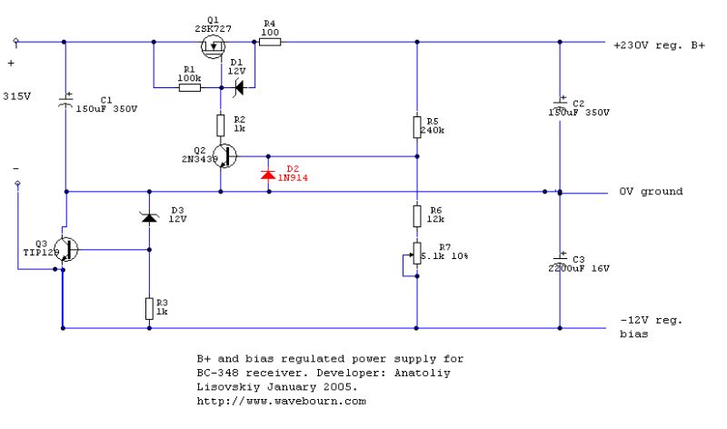
To further limit the current you may move it's right leg through the R4 resistor.
this is a nice design for a regulator. Can I ask why no bypass cap on R5? From R5 to the base of Q2. That is common to reduce the HF impeadence of the supply.
The whole topic is like religion. You have the "God made man in his image" type (Only tubes in everything), the "There is a Higher Power and Evolution is how we came about" (Lets use SS diodes and transistors in non audio path areas) and "There is no God! Science Rules!" ( They are in the Solid State forum) . I hope you understand the point I make. I'd like an A/B/X test of the different PS regs.
The whole topic is like religion. You have the "God made man in his image" type (Only tubes in everything), the "There is a Higher Power and Evolution is how we came about" (Lets use SS diodes and transistors in non audio path areas) and "There is no God! Science Rules!" ( They are in the Solid State forum) . I hope you understand the point I make. I'd like an A/B/X test of the different PS regs.
Wavebourn said:Foollowing the topic created by CarleBoy, I would like to open discussion to shed a light, if tube power regulators have some advantage over solid state voltage regulators. It is the first question, when some device has advantage, before answering how to build it.
I wanted to get the answer "why?" right in the topic "how?", but I am afraid the question may sink in a flame.
- Glowey bottles coolness.
- No heat sinks several hundred volts above ground.
- VTs don't go "poof" nearly as easily.
- Gas discharge voltage references are more accuarte than HV Zeners, quieter, and the noise component is a good deal softer than reverse bias PN junction noise.
I always wondered why no one has tried using a cheap transmitting tube like an 811A as a pass element. Its needs posetive grid bias so a solid state front end could drive it easily.
Well, I am. The PS for the 845 amp I'm working on will use an 811 as a parallel regulator for the main plate supply.
Re: Re: Tube VS SS voltage regulators - any advantages?
Yes, you may reduce own dynamic resistance on high frequencies of the regulator (without output capacitor), but in case of shorted output you'll get a pulse of voltage between base and emitter that may exceed 5V and damage the transistor. It is better to use output capacitor, anyway the regulator is far better than a passive filter with chokes and capacitors. But as soon as a diode present, you may use a capacitor. Also, one more zener may be used to limit maximum output current, as I described above, in this particular case 12V Zener will limit on about 50 mA, if to decrease resistor in source proportionally the limited current will be higher.
Also, the main feature of this regulator is a soft start. It was designed to power vacuum tubes. When tubes are cold they don't draw a current, and voltage on the output of the regulator goes up slowly; when tubes are hot and start drawing current due to positive feedback it increases output voltage untill it is stable. This regulator extends life of tubes powered by it, also it minimizes impact of transcient processes when switched on, despite it is so simple and contains very few elements.
TUBESMAN said:this is a nice design for a regulator. Can I ask why no bypass cap on R5? From R5 to the base of Q2. That is common to reduce the HF impeadence of the supply.
Yes, you may reduce own dynamic resistance on high frequencies of the regulator (without output capacitor), but in case of shorted output you'll get a pulse of voltage between base and emitter that may exceed 5V and damage the transistor. It is better to use output capacitor, anyway the regulator is far better than a passive filter with chokes and capacitors. But as soon as a diode present, you may use a capacitor. Also, one more zener may be used to limit maximum output current, as I described above, in this particular case 12V Zener will limit on about 50 mA, if to decrease resistor in source proportionally the limited current will be higher.
Also, the main feature of this regulator is a soft start. It was designed to power vacuum tubes. When tubes are cold they don't draw a current, and voltage on the output of the regulator goes up slowly; when tubes are hot and start drawing current due to positive feedback it increases output voltage untill it is stable. This regulator extends life of tubes powered by it, also it minimizes impact of transcient processes when switched on, despite it is so simple and contains very few elements.
Miles Prower said:
- Glowey bottles coolness.
I've asked about technical reasons.
[*]No heat sinks several hundred volts above ground.
Again, it is not a technical reason, nobody forces you to expowe high voltages. Insulation is cheap.
[*]VTs don't go "poof" nearly as easily.
Again, it is not a technical reason, but a style of handling. Tubes may be easily damaged as well. For example, they are fragile and may fall...")
[*]Gas discharge voltage references are more accuarte than HV Zeners,
Please show any "less accurate" HV zener in my regulator. Zeners may be thermally compensated, unlike gas dischaarge stabilizers...
quieter, and the noise component is a good deal softer than reverse bias PN junction noise.
Again, it is not a technical reason, but result of poor usage. You are not forced to amplify noises, but you can easilly shunt them by capacitors. Also, you may use your gas discharge cool glowing tube with transistors. However, as the result you will get a peak of voltage while the gas discharge stabilizer starts, but anyway it is less dangerous than a broken tube that causes output voltage to be very high and unregulated.
Well, I am. The PS for the 845 amp I'm working on will use an 811 as a parallel regulator for the main plate supply.
- And of course, you amplify noises, expose high voltages, and drop tubes from the table?
I don't think so...
I'm inclined to agree with jarthel here. One of the biggest disadvantages of series tube regulation I believe is the raher high plate-to-cathode voltage requirement, which means that you need a higher input voltage to a tube series regulator than you would with an SS series regulator, for a given output voltage and current draw.
Modern MOSFET devices seem able to work at realistic voltages for supplying tube circuits. Proper care in their use should not result in damage. Their high gain promises excellent regulation and the only possible downsides I can see to MOSFET regulation are the need for heatsinks and, possibly, more noise. Heatsinks can be provided safely, with a little skill, but I don't know enough about what noise could be introduced in MOSFETS and zeners to feel confident about how easily it could be overcome.
Modern MOSFET devices seem able to work at realistic voltages for supplying tube circuits. Proper care in their use should not result in damage. Their high gain promises excellent regulation and the only possible downsides I can see to MOSFET regulation are the need for heatsinks and, possibly, more noise. Heatsinks can be provided safely, with a little skill, but I don't know enough about what noise could be introduced in MOSFETS and zeners to feel confident about how easily it could be overcome.
A tube will also have more noise because its transconductance is much lower than a power transistor/MOSFET. Objectively, tube regulators are noisier, driftier, less efficient, and have higher source Z. I can argue about the superiority of tubes for audio amplification, but this is DC- some time spent looking at the rails of a regulator with music playing through the device loading it is very instructive. It certainly instructed me to run from tube regs at full speed.
Re: Re: Re: Tube VS SS voltage regulators - any advantages?
Although, it is a practical reason. Even though the transistor is insulated from the heatsink the tab will have high voltage on it. Assuming that the heatsink is mounted on the outside of the chassis to give good cooling, does anyone have a way, short of a cage, to protect the tab from being touched?
Dave
Wavebourn said:
quote:
[*]No heat sinks several hundred volts above ground.
Again, it is not a technical reason, nobody forces you to expowe high voltages. Insulation is cheap.
Although, it is a practical reason. Even though the transistor is insulated from the heatsink the tab will have high voltage on it. Assuming that the heatsink is mounted on the outside of the chassis to give good cooling, does anyone have a way, short of a cage, to protect the tab from being touched?
Dave
Dave,
If you use a TO-3 style pass transistor, you can buy plastic covers to shield the high voltage can (a tiny hole allows a slender probe to enter for test, but not a finger). If the pass transistor is a TO-220 style or one of its variants, it could be placed on the inner side, or in the inner chamber, of an external heatsink to avoid contact. There are insulated-tab variants of the TO-220, but you've still got three exposed hot pins to worry about.
If you use a TO-3 style pass transistor, you can buy plastic covers to shield the high voltage can (a tiny hole allows a slender probe to enter for test, but not a finger). If the pass transistor is a TO-220 style or one of its variants, it could be placed on the inner side, or in the inner chamber, of an external heatsink to avoid contact. There are insulated-tab variants of the TO-220, but you've still got three exposed hot pins to worry about.
fdegrove said:Hi,
Why do I get the feeling there'll be plenty more racks in the pool.
Because it is the common practice. A new generation of engineers use computer simulators and barely touch an iron. As the result, it is easier to grab parts of schematics from libraries and put them together without thinking how to get the same result using minimal necessary set of elements drilling less holes, fighting against parasitics, transients, and other side effects. .
The same unfortunately happens with tubes when people tend to search in vintage popular magazines for kids, mass production schematics, stupid patents, instead of applying own gray substance.
- Status
- This old topic is closed. If you want to reopen this topic, contact a moderator using the "Report Post" button.
- Home
- Amplifiers
- Power Supplies
- Tube VS SS voltage regulators - any advantages?