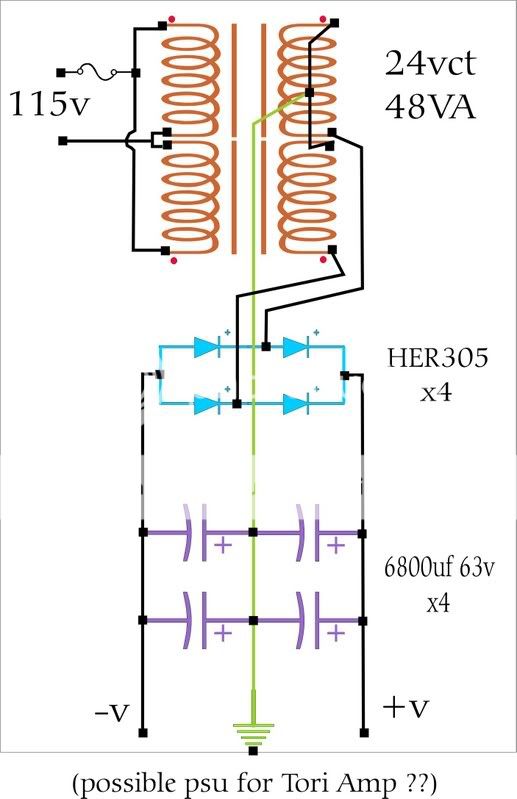
This is a capacitance PSU for my Tori headphone amp .
.....no other regulation.
What is the formula for adding a CRC filter to this PSU?
I'd like to add this filter for 2 reasons: ripple rejection, and hopefully reduce the voltage a little.
Right now, it gives me about (+-)18v under a 500 ohm load (2 test resistors).
The Xformer I'm using is not the 48VA shown, but a 24VA I found under my couch.
This drawing uses schematic symbols, but in a "parts layout" fashion.......(those secondary wires are supposed to go under the tranny, not connected to it's mid-point, in some weird way.....just standard.)
I added a 0.1uf cap across the secondary, before the rectifiers, too.
(HER305):
http://www.diodes.com/products/inactive/category.php?category=a-h
Would a series resistor between the 6800uf caps become a CRC?.....or do I add a CRC after those smoothing caps.
Thanks soooo.... much,
much,
=RR=
.....no other regulation.
What is the formula for adding a CRC filter to this PSU?
I'd like to add this filter for 2 reasons: ripple rejection, and hopefully reduce the voltage a little.
Right now, it gives me about (+-)18v under a 500 ohm load (2 test resistors).
The Xformer I'm using is not the 48VA shown, but a 24VA I found under my couch.
This drawing uses schematic symbols, but in a "parts layout" fashion.......(those secondary wires are supposed to go under the tranny, not connected to it's mid-point, in some weird way.....just standard.)
I added a 0.1uf cap across the secondary, before the rectifiers, too.
(HER305):
http://www.diodes.com/products/inactive/category.php?category=a-h
Would a series resistor between the 6800uf caps become a CRC?.....or do I add a CRC after those smoothing caps.
Thanks soooo....
much,=RR=
Hi,
You can add a pair of series resistors between the caps.
or
add an extra RC after the double caps.
Both methods will give you a CRC supply.
BTW. the transformer resistance gives you a RCC at present and becomes RCRC if you add that extra resistor.
The first cap sees almost all the mains ripple and must be rated for that ripple duty. Otherwise it could end up with a VERY short life. Fortunately your load current is fairly low (ClassA will ripple load that first cap).
The continuous current to the load determines the voltage drop across the resistors. So choose your resistor value to drop the voltage you don't need.
The filter behaves like any other filter. It reduces the mains AC frequency and lets through the DC component.
Adding a 180mS (6800u*27r) filter by using a 27r dropper will significantly reduce the ripple seen by the load. MUCH MUCH better than keeping the doubled up C filter.
I think the sound quality is determined mostly by the last C of a CRCRC smoothing bank. Spend good money on it. For a headphone amp it might be economic to choose plastic film motor run caps for the final C. I do not think exotics costing a small fortune are good value here (and possibly not anywhere).
If you download psud2 you can examine ripple current and output ripple using your CC, CRC, CCRC options and decide which to use.

Mostly, yes.
Q:
Am I correct in thinking the filter is targeting a certian freq (ripple),(creating a knee at that freq) ?
........and if I'm using full-wave rectification, I double the standard mains ripple freq when configuring the filter ?
Q2:

=FB=
Q:
Am I correct in thinking the filter is targeting a certian freq (ripple),(creating a knee at that freq) ?
........and if I'm using full-wave rectification, I double the standard mains ripple freq when configuring the filter ?
Q2:
rated how ?......voltage wise, impeadance wise...?The first cap sees almost all the mains ripple and must be rated for that ripple duty.
=FB=
Built it today.
I used the larger 48VA Xformer, so I needed smaller size caps....to fit in the case. I'd rather have used 35v or 50v caps but 3@4700uf 25v is what I had....hmmmm...
The resistor is in series just before the last cap.
I played around with PSUdesignerII a bit, and it said that with a 27 ohm resistor, I'd get around 9v at load (50 ohm).
So strangly, I went with 2.2 ohms. It said I would get 11 volts.
I'm sure I inputed wrong component info. Need to research that.
It's outputing 18.5v unloaded, and 15.3v w/50 ohm resistors on the output(s)...... and pushing 0.6 amps.
I have my first scope, um....how do I check the ripple?
My guesses.....hook it to output, switch to read AC, then I'm not sure what to look for. I've done this, but I must switch to maybe 0.1v/5ms....and the view is fuzzy...I'm lost at this simple test.
Hey look!! I can change the resistors easily.
=RR=
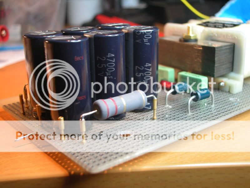
I used the larger 48VA Xformer, so I needed smaller size caps....to fit in the case. I'd rather have used 35v or 50v caps but 3@4700uf 25v is what I had....hmmmm...
The resistor is in series just before the last cap.
I played around with PSUdesignerII a bit, and it said that with a 27 ohm resistor, I'd get around 9v at load (50 ohm).
So strangly, I went with 2.2 ohms. It said I would get 11 volts.
I'm sure I inputed wrong component info. Need to research that.
It's outputing 18.5v unloaded, and 15.3v w/50 ohm resistors on the output(s)...... and pushing 0.6 amps.
I have my first scope, um....how do I check the ripple?
My guesses.....hook it to output, switch to read AC, then I'm not sure what to look for. I've done this, but I must switch to maybe 0.1v/5ms....and the view is fuzzy...I'm lost at this simple test.
Hey look!!
I can change the resistors easily. =RR=
I apologize.
I was just using 500r as a safe load to test it functionaly, and see if anything heats up with a lighter type load.
I switched to testing with 50 ohm resistors because I thought they were closer to the Tori's draw.
I do not know the power load (in ohms) required for my Tori amp.
I wish I knew how to calculate that.
What I do know is that when connecting the Tori to my spare 317/337 1.2amp regulated PSU, the Tori (at idle) was drawing about 0.6 amps/@ 12v.
The first Cap PSU I built used a smaller Xformer (24VA), and if I am correct, because of the above test, that's not enough juice.
So for the second attempt (pic above), I upped the Xformer to a 48VA but found the 6800uf caps would not fit, hence the 4700uf's.
In these "no-regulator" psu's I've just build, I was suprised to see the volts drop like that when powering the Tori:
PSU unloaded 18v
PSU w/Tori 12-15v (a good range)
.....so I do not believe I need to reduce the PSU's voltage, just wrangle the ripple as best I can.
I got a little impatient, and started putt'n parts to solder. I only have weekends these days to build stuff
I'm not concerned if must rebuild it because there is a better way. I have plenty of parts, and it's great fun too.
Of course, I am deeply interested in learning to do it correctly, and proffesionaly. If I wasn't, I'd already have a working hissy headphone amp that may or may not work in a month ....and/or build things from a "kit"..........building from scratch is more satisfying to me.
Your help has been just that, very, very helpful . I am still "all ears"
=RR=
I was just using 500r as a safe load to test it functionaly, and see if anything heats up with a lighter type load.
I switched to testing with 50 ohm resistors because I thought they were closer to the Tori's draw.
I do not know the power load (in ohms) required for my Tori amp.
I wish I knew how to calculate that.
What I do know is that when connecting the Tori to my spare 317/337 1.2amp regulated PSU, the Tori (at idle) was drawing about 0.6 amps/@ 12v.
The first Cap PSU I built used a smaller Xformer (24VA), and if I am correct, because of the above test, that's not enough juice.
So for the second attempt (pic above), I upped the Xformer to a 48VA but found the 6800uf caps would not fit, hence the 4700uf's.
In these "no-regulator" psu's I've just build, I was suprised to see the volts drop like that when powering the Tori:
PSU unloaded 18v
PSU w/Tori 12-15v (a good range)
.....so I do not believe I need to reduce the PSU's voltage, just wrangle the ripple as best I can.
I got a little impatient, and started putt'n parts to solder. I only have weekends these days to build stuff
I'm not concerned if must rebuild it because there is a better way. I have plenty of parts, and it's great fun too.
Of course, I am deeply interested in learning to do it correctly, and proffesionaly. If I wasn't, I'd already have a working hissy headphone amp that may or may not work in a month
....and/or build things from a "kit"..........building from scratch is more satisfying to me.Your help has been just that, very, very helpful . I am still "all ears"
=RR=
Hi,
two things that may have been overlooked:-
Transformer regulation and maximum current from the transformer into a capacitor input PSU.
The transformer regulation tells you how much the open circuit voltage exceeds the fully loaded output voltage when driving a resistive load.
If your transformer is specified as 12Vac from 230Vac and 10% regulation, then it will produce 12 * 1.1 = 13.2Vac from 230Vac. But if the mains voltage varies then you need to correct the transformer output voltage.
The capacitor input PSU loads up the transformer very inefficiently and this causes more heat in the windings than when driving a pure resistance as a load.
The net effect is that the continuous DC current from the rectifier and smoothing caps is about half the rated AC current (this is the 0.7 derating quoted by many designers, manufacturers and commentators).
Using your numbers 24VA and 12+12Vac gives an AC current <=1000mA.
You can draw 500mA maximum continuous current drawn equally from twin secondaries (@ 18Vdc).
A ClassA amplifier is very hard on both the transformer and the smoothing caps. (600mA is over a safe current for a 24VA twin secondary - 50VA seems more like a sensible start)
- Status
- This old topic is closed. If you want to reopen this topic, contact a moderator using the "Report Post" button.
- Home
- Amplifiers
- Power Supplies
- CRC filter values....method? (w/schemo)