I have electronic key board and it requires 16volts 2.5 A regulated power supply.Now i'm having 230 volts 12-0-12 ,5Amperes Transformer.So please help me how i can construct 16 volts 3 A regulated power supply using 12-0-12 volts Transformer.
Any help is highly appreciated.
Thanks,
SUNNY
Any help is highly appreciated.
Thanks,
SUNNY
Hi:
The maximum current of the LM317 is 1.5A, which is not enough. The LM338 might be a better choice. Anyways, I think that in this particular case it would be better to use a switching-type regulator (due to power dissipation issues associated with linear regulators such as the LM338). Best yet would be to buy a suitable switching power adapter used for notebooks.
Regards,
Milan
Hi Sunny,
the 12Vac will give about 17Vdc after the rectifier and smoothing caps.
This is too low to drive a regulator and get 16Vdc output.
Series connecting the 12+12 will give 34Vdc. This is way over Pink's estimate of 24Vdc.
The regulator will have to lose 18V to get down to your 16Vdc.
At 2.5A continuous the regulator will have to dissipate 2.5 times 18 = 45W. This will need an enormous passive sink or a big fan cooled sink.
Does your supply need to be regulated?
What if you fed the 17Vdc from the smoothed PSU straight into your circuit? After the rectifier the voltage will be about 16Vdc when fully loaded to 120W.
A slight problem may be the regulation of your transformer. The open circuit voltage will be higher than 12Vac and the rectified DC will also be higher until you load the transformer.
You could have 18.5Vdc if the regulation is 10%. Take off your diode drop and you may have about 17 to 17.5Vdc before you load up the transformer.
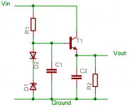
How clean does the regulated voltage have to be? Why does everyone always overlook the very simple but effective emitter follower with a zener reference? To get the 16V output you can put a regular diode in series with a 16V zener to get about 16.5-16.7V at the base of the NPN transistor. Alternatively, you could use the base-emitter junction of another transistor of the same type that is used as the pass element as the diode in series with the zener to get a more closely matched voltage.
Attachments
Thanks for your response.I'm the new member to this forum,so i cannot send the personal e-mail.So kindly send me the circuit diagram to my e-mail address
sunny152s@rediffmail.com
Thanks,
SUNNY.
sunny152s@rediffmail.com
Thanks,
SUNNY.
Sunny,
Too bad you can't do the LM2576 SimpleSwitcher buck regulator. I'd have that puppy built in a day.
But, as you say, you need it for 12-0-12V Xfmr, so how about this:
Do a conventional transformer-rectifier-inductor-capacitor set-up to get the ~17.8V unregulated output. Then feed this into an LM2587-ADJ SimpleSwitcher IC set up as a flyback. Set the feedback up for a 16V output. Since the '2587 is rated sor 5A (6-6-7A peak), you should be able to recover at least 3.0A from the secondary side. And, because the switching frequency is 100kHz, your output caps and inductors can be rather small.
Here is the National Semiconductor datasheet on the '2587: http://cache.national.com/ds/LM/LM2587.pdf
This way, you will get the best of both worlds: use of your 240-12V trafo, and clean, efficient regulation with little-to-no heat dissipation.
Cheers,
Steve
Look at my recent post. There is a diagram. It produces just over 18v unloaded, using a 12-0-12v transformer.
The pic shows you everything that comes just before adding the regulators .
It's easy. Use any rectificier you want that exceeds your needs.
(I am not using a regulator.....why?.....because, of course I can use one, but I've never tried it without one, and, in my circuit it's not necessary.)
http://www.diyaudio.com/forums/showthread.php?s=&threadid=88761
=RR=
Hi Panicos,
I recieved the circuit diagram,pictures and i'm very thankful to you.I have some queries about the circuit diagram,please clarify.
1.Can i use my transformer 12-0-12 for this power supply?
2.what is the output voltage of this circuit?
3.will you please suggest fixed value resistors instead of variable resistors to get 16volts at the output?
Please clarify.
Thanks,
SUNNY.
Sunny, 1)Yes you can use your transformer,just use the two 12V wires to get 24V to the AC input of the board, 2)for the 16vdc you want R2 should be around 2K9. R1 is almost standard at 240R. 3)Output of this circuit depends on the chosen R2 value and the transformer used.By following the formula you can easily calculate R2 and therefore DC output. Vout=(1+R2/R1). Make sure that your transformer can deliever 3A. If you'll follow the circuit I sent you,provide enough space for the rectifier to be used,as the space on my board is for W02 rectifier which is rather small.If you need any further I'm here.
HelloPanicos,
I have calculated the value of R2 as per the formula and the R2 value is 3.6K and still i have some questions ,please clarify.
1.What should be the wattage of R1 ?Can i use 5% tolerence resistor?
2.Please suggest one fixed standard value resistor for R2 and its wattage and tolorence.
Waiting for your reply.
Thanks,
SUNNY.
- Status
- This old topic is closed. If you want to reopen this topic, contact a moderator using the "Report Post" button.
- Home
- Amplifiers
- Power Supplies
- 16 volts 3A regulated power supply help