I just purchased toroidal trnasformer for a LM338 regulated power supply for LM3886. I ordered 2 x 30v sec. (300VA). But the transformer giving 2 x 32v. So after the bridge rectifier I will get around 45v approx. Is this supply safe for LM338? The datasheet of the regulator says max input voltage is 40v.
I want 35volt output from the regulator.
Thanks in advance for any suggestion...
I want 35volt output from the regulator.
Thanks in advance for any suggestion...
thanks
thanks Tweeker. i read about it in the datasheet, but never saw an example with large input voltage till i searched the net like mad.
i have another concern. the regulator can supply around 5 amp current. is this independent of the input voltage as along as Vin-Vout<35v?
thanks Tweeker. i read about it in the datasheet, but never saw an example with large input voltage till i searched the net like mad.
i have another concern. the regulator can supply around 5 amp current. is this independent of the input voltage as along as Vin-Vout<35v?
... and another thing ...
Just because the spec sheet says "up to 35 DVC" does not mean success in all cases. The Absolute Maximum is just that = absolute. If there is any ripple or surges coming from upstream then = no joy
http://www.national.com/ds/LM/LM138.pdf ...
Here is a neat trick however ... you can use a daisy chain of diodes to "knock down" the incoming voltage = each diode = 0.6 VDC throw away = 10 diodes = 6 VDC down.
You can also do the same daisy chain on the ground leg 'tween the adjustable resistor and ground ...
Re: thanks
You need to check the load/SOA lines in the datasheet for your application.
Roushon said:The regulator can supply around 5 amp current. is this independent of the input voltage as along as Vin-Vout<35v?
You need to check the load/SOA lines in the datasheet for your application.
That won't do it !!
Roushon: " ... using series of diodes to drop the voltage is really a nice idea. i think it will be even better to use more diodes in series in the rectifier stage itself. ..."
Warning: the use of diodes in a daisy chain (stacked / chained in series) from a pure AC source (like right outta the transformer to the rectifier diode bridge) is NOT advised. This is how higher voltages can be generated, not lower voltages !!! (the AC peaks get "pumped up" in the diode series ... This daisy chain of diodes is sometimes used in old radio circuits to increase peak voltage (!!!!) = a bad idea for AC circuits, but fine for well filtered DC only.
Try something else !
(The use of a daisy chain of diodes to "drop" DC voltage is an old solar power supply trick as published in Popular Electronics circa 1989 ... I know 'cause I wrote it up)
Roushon: " ... using series of diodes to drop the voltage is really a nice idea. i think it will be even better to use more diodes in series in the rectifier stage itself. ..."
Warning: the use of diodes in a daisy chain (stacked / chained in series) from a pure AC source (like right outta the transformer to the rectifier diode bridge) is NOT advised. This is how higher voltages can be generated, not lower voltages !!!
(the AC peaks get "pumped up" in the diode series ... This daisy chain of diodes is sometimes used in old radio circuits to increase peak voltage (!!!!) = a bad idea for AC circuits, but fine for well filtered DC only.Try something else !
(The use of a daisy chain of diodes to "drop" DC voltage is an old solar power supply trick as published in Popular Electronics circa 1989 ... I know 'cause I wrote it up)
>This is how higher voltages can be generated, not lower
>voltages !!! (the AC peaks get "pumped up" in the diode series
There's no "pumping" to a higher voltage unless you specifically connect up diodes and capacitors in a multiplier (cascaDe) circuit, like those used in CRT HV supplies.
Diode drops are fine when you need a small voltage drop. In Roushon's case, an extra transistor is much safer. See http://www.national.com/an/LB/LB-47.pdf for a circuit.
Pumped?
" ... There's no "pumping" to a higher voltage unless you specifically connect up diodes and capacitors in a multiplier (cascaDe) circuit, like those used in CRT HV supplies. ..."
If poor wiring practices are used, the stray capacitance could conceivably cause the voltage to pump up, possibly much more than the 0.6 volts "lost" to the diode barrier. ... I would not recommend diodes in series passing AC = too unpredictable ... (Diodes in parallel are another matter.)
Re: Pumped?
Not so fast, Eddy!
I think you got that reversed.
Series diodes are fully predictable: each conducts the same current, and even if the conduction voltages vary, they nicely add up anyway.
But if you parallel them, the slight difference in conduction voltage makes one diode conduct more current than the other -> entirely UNpredictable who conducts what.
Jan Didden
FastEddy said:" ... There's no "pumping" to a higher voltage unless you specifically connect up diodes and capacitors in a multiplier (cascaDe) circuit, like those used in CRT HV supplies. ..."
If poor wiring practices are used, the stray capacitance could conceivably cause the voltage to pump up, possibly much more than the 0.6 volts "lost" to the diode barrier. ... I would not recommend diodes in series passing AC = too unpredictable ... (Diodes in parallel are another matter.)
Not so fast, Eddy!
I think you got that reversed.
Series diodes are fully predictable: each conducts the same current, and even if the conduction voltages vary, they nicely add up anyway.
But if you parallel them, the slight difference in conduction voltage makes one diode conduct more current than the other -> entirely UNpredictable who conducts what.
Jan Didden
Perfect!!
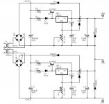
Roushon !!! That circuit will do very nicely. And as long as you don't try to make the regulators drop below about +/- 10 VDC output, the chip(s) will survive and not run hot. (I would still suggest heat sinks on the reg. chips.)
An ~ 1.5K to 2K resistor between R2 and ground and between R12 and the negative rail (-V) would lock out this question ... giving adjustable output voltage range of ~ 10 VDC and your required 40 VDC. (There is an exact formula for this from the chip makers = check it out.)
For nearly perfect balance you might consider adding a 1N4004 diode located between C13 and R12 ... and another 1N4004 diode located between C3 and R2 ... (both properly polarized, of course) ... complimenting D1 and D11.
Good show:
Roushon said:i just found the attached circuit.
Roushon,
There is one potential risk here: at switch-on, the decoupling caps on the adjust pins have zero volts. It takes time for them to charge. At switch-on, therefore, the regulator will see the full input voltage -> BOOM, unless the adjust decoupling caps charge at least as fast as the input voltage rise. Difficult to predict, but you have been warned!
Jan Didden
Who's half fast?
janneman: " ... Not so fast, Eddy! ... I think you got that reversed. ... Series diodes are fully predictable: each conducts the same current, and even if the conduction voltages vary, they nicely add up anyway. ... But if you parallel them, the slight difference in conduction voltage makes one diode conduct more current than the other -> entirely UNpredictable who conducts what. ..."
Series diodes are "fully predictable" when careful attention is paid to wiring practices and design ... but if you find a significant amount of (stray) capacitance between a couple of diodes in series ...
This was a common problem in the early days of CMOS digital chip technology ... using a couple of series diodes between the power rails to "clamp" the inputs on CMOS chips = if this was done with even a small amount of stray capacitance = pop goes the chip from over voltage, static or surge. (This problem is now solved by incorporating the clamping diodes right on the silicon, minimizing the stray capacitance ... using my hero's inventions, Walter Schottky, inventor of the first solid state semiconductors, high performance Schottky Barrier diodes, the screen grid vacuum tube, and discoverer of the "tunnel diode" effect ... a DIY laboratory hardware hacker of the first water ( http://en.wikipedia.org/wiki/Walter_H._Schottky ) .)
As for parallel diodes, they are very predictable as thermally induced resistance tends toward uniform current throughput in multiple, parallel diode arrays ... heat adding resistance in each diode, greater heat = greater resistance
And it is possible to make quite good, predicitable, small signal detectors from paralleled diodes = greater tunneling and sensitivity by a factor of N x S (#diodes times individual diode sensitivity + a Constant) ... basically ten parallel diodes being 10 times as sensitive as one ...
So, you are right about the predicitability of a single diode in a parallel array of diodes, but in an array of two or more diodes, the degree of predicitability increases for the diode array as a whole, not the other way around ... the array tending toward the thermal and resistance mean.
....
I recently obtained a copy of Mr. White's book ... wonderful stuff ...
Re: Perfect!!
thanks. but Janneman raised a doubt about the circuit. i will see the circuit suggested by Wine&Dine from the National page. there the circuit is around Lm317 and the voltage difference has been kept fixed to 5v using a zener. at the moment i do not know if i can implement that idea here.
thanks for pointing out the risk. if you have any suggestion please elaborate. i have one as described above, but not sure.
FastEddy said:Roushon !!! That circuit will do very nicely. And as long as you don't try to make the regulators drop below about +/- 10 VDC output, the chip(s) will survive and not run hot. (I would still suggest heat sinks on the reg. chips.)
An ~ 1.5K to 2K resistor between R2 and ground and between R12 and the negative rail (-V) would lock out this question ... giving adjustable output voltage range of ~ 10 VDC and your required 40 VDC. (There is an exact formula for this from the chip makers = check it out.)
For nearly perfect balance you might consider adding a 1N4004 diode located between C13 and R12 ... and another 1N4004 diode located between C3 and R2 ... (both properly polarized, of course) ... complimenting D1 and D11.
Good show:
thanks. but Janneman raised a doubt about the circuit. i will see the circuit suggested by Wine&Dine from the National page. there the circuit is around Lm317 and the voltage difference has been kept fixed to 5v using a zener. at the moment i do not know if i can implement that idea here.
janneman said:
Roushon,
There is one potential risk here: at switch-on, the decoupling caps on the adjust pins have zero volts. It takes time for them to charge. At switch-on, therefore, the regulator will see the full input voltage -> BOOM, unless the adjust decoupling caps charge at least as fast as the input voltage rise. Difficult to predict, but you have been warned!
Jan Didden
thanks for pointing out the risk. if you have any suggestion please elaborate. i have one as described above, but not sure.
Re: :>)
No.
No.
Is this a job offer?
Jan Didden
FastEddy said:Thanks ... and you are good at spotting oddities of design.
I would also bet that you do this kind of thing for a living ... or teach it somewhere ...
No.
No.
Is this a job offer?
Jan Didden
janneman said:
Roushon,
There is one potential risk here: at switch-on, the decoupling caps on the adjust pins have zero volts. It takes time for them to charge. At switch-on, therefore, the regulator will see the full input voltage -> BOOM, unless the adjust decoupling caps charge at least as fast as the input voltage rise. Difficult to predict, but you have been warned!
Jan Didden
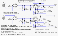
Do the same risk apply to the following circuit?
Attachments
- Status
- This old topic is closed. If you want to reopen this topic, contact a moderator using the "Report Post" button.
- Home
- Amplifiers
- Power Supplies
- LM338 regulator InputMax voltage..