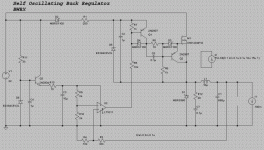
I've been working on a swithing supply that's self oscillating and so far it simulates pretty well.
It's a buck regulator, at the heart of which is a comparator. This comparator, in conjunction with a reference voltage and feeback after the output filter, creates the switching pulses that are current coupled to the N-channel mosfet driver.
The LT1011 has an open collector output which makes it easy to current couple to the high side driver. If this high side driver looks familiar that's because it's basically the same one used in the self oscillating class D UcD amplifiers, only this incorporates a speed up cap. The supply for the high side driver uses the standard bootsrap configuration, but I've added a zener clamp since the unregulated supply voltage could be rather high. A series resistor could be added for use with even higher input voltages.
The reference voltage is derived from a filtered and buffered zener, some more filtering and a resistive divider, and is fed to the inverting input. Feedback is taken post output filter and is fed to the non inverting input.
Output noise is pretty good for a switching supply and it works with input voltages 18V and higher and is configured to output 12V. You can change the output current load and also add a pulsed current load and see what happens in the simulations. The regulator works pretty well with the components I picked right off the bat, but could probably be better with better parts.
It simple enough that you could throw it together on a bread board and doesn't require very expensive parts. I plan on building one in the near future, but if anyone beats me to it let me know how it works!
Any ideas for improvement are most certainly welcomed!
Attachments
I tweaked the design a bit and it knocked the noise floor down a little more. If it's actually as good as it simulates then it would make a good supply for a preamp.
The noise floor rises to about -100dB with a 12ohm load resistor and 20ma current source, but that's still pretty good.
The supply also handles large current pulses well. You can attach a current source as a load and set it up to quickly pulse a 3A draw and see for yourself how the regulator handles it.
The FFT plot was calculated from a 3ms to 10ms window of the output voltage. If you include the start up portion of the output voltage then the FFT plot doesn't give accurate steady state results.
Attachments
You could use a different comparator. I picked the LT1011 because it's pretty fast, its output transistor is floating, can source a fair amount of current, and can handle up to 40V absolute max between the output and the negative supply rail. It should be fine as long as the input voltage doesn't go much higher than about 25V.
Alternatively you could put a bjt or mosfet at the output to further protect the comparator output. If it were a mosfet I would connect the gate to the comparator's supply, the drain to the upper mosfet driver, and the source to the comparator's output.
Alternatively you could put a bjt or mosfet at the output to further protect the comparator output. If it were a mosfet I would connect the gate to the comparator's supply, the drain to the upper mosfet driver, and the source to the comparator's output.
- Status
- This old topic is closed. If you want to reopen this topic, contact a moderator using the "Report Post" button.
- Home
- Amplifiers
- Power Supplies
- Fairly simple, relatively discrete switching regulator
