I need a good power supply design that can handle two symasm4's and is possibly switchable power output. it needs to be low-hum and I am also wanting to run my 3-amp CB radio off of it. It doesn't necessarily need to be my exact specifications- it just needs to be versatile enough to fit my needs. I am trying to set up a somewhat hi-fi audio amp in my house with as little money as possible so I would prefer it to be low-cost, but good. If you know of another design that is good but not necessarily low-cost feel free to post, though. any replies are greatly appreciated! 
Hi,
you specify Low Hum, why?
Do you know that either of the amps you intend to hang on the output have a bad PSRR?
A standard rectifier/smoothing capacitor PSU is hum free for most well designed amps.
Incorrect grounding can and often does cause hum.
PS. cap multiplier certainly reduces output ripple, at a slight cost of slightly reduced output voltage.
Hmm. I still want a good design though. If I can manage to build one, I wouldn't just trash it with everything else when my amp blew out, I would use it for other things too. I was wondering about the 4QD supply here:
http://www.4qdtec.com/psu1.html
Any modifications? Know of a better one? I'm serious about this. Thanks for any response!
http://www.4qdtec.com/psu1.html
Any modifications? Know of a better one? I'm serious about this. Thanks for any response!
Hi,
36Vdc is quite low for a power amp. It will need a dual secondary 25Vac transformer. Centre tapped 25-0-25 will do just as well, unless Symasim say otherwise. A four secondary each @ 25Vac would be ideal but they tend to be expensive.
The 13.8V sounds like it might need to be regulated. Therefore your loaded input voltage will need to be about 16Vdc to 17Vdc requiring a 13Vac transformer. 12Vac might just do, but it leaves just 1.5Vdc through the regulator. That will drop out on low mains input voltage. 12Vac would need to be an LDO high current type.
VA rating would be 2*3*13=80VA due to the capacitor loading after the rectifier.
You could use a 15Vac 100VA transformer but that would increase the dissipation in the regulator and would require an enormous heatsink or blown.
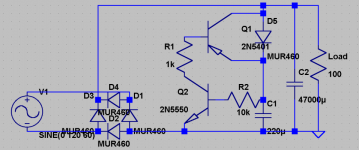
D5 charges C1, wich upon full charge triggers Q2 which triggers Q1 and regulates current in accord with the fluctuations. C2 regulates voltage. I think connecting a 2K resistor between + and Q1's base might help the freakishly overdone voltage... Any suggestions?
C1 can be increased for better current stability and the same for voltage with C2.
C1 can be increased for better current stability and the same for voltage with C2.
I faled to clarify something on my design: when Q1 is triggered, it allows current to flow from C1and smoothen out the current. I am wondering if I could use JFET to regulate voltage in the same fasion for the sake of cost. Actually I haven't the slightest idea about regulators and power supply's, so I do not know any terms. So go easy on me, okay?
Currently the circuit is doing the opposite of regulating current, so I am trying to implement an inverting regulation setup. Please don't be repelled by my lack of experience! I just thought about checking out this design.
I figured out that the over-voltage from Q1 is coming from it's emitter, so I will see if a current limiting resistor will do the trick.
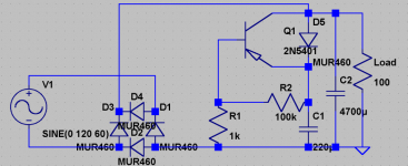
This time I use one PNP transistor and a voltage divider to bias it (of course). C2 is not completely necessary, except to regulate the voltage.
One gain is that it handles 10A better.
I have also noticed that placing a resistor just before Q1's base helps smoothen current but slightly increases voltage fluctuations.
One gain is that it handles 10A better.
I have also noticed that placing a resistor just before Q1's base helps smoothen current but slightly increases voltage fluctuations.
Assuming there is a resistor (R3) just before Q1's base, I have found that:
for 1A-2A R3=1M nominal.
for 3A-5A R3=680k nominal.
for 10A R3=470k nominal (this isn't as good regulation).
If you need more current regulation and not necessarily as much voltage regulation, increase R3. If you need more voltage regulation and not necessarily as much current regulation, increase C2.
NOTE: These values were found on a simulator so expect them to be a bit off.
keantoken,
I do not wish to discourage you, but you really need to take a step backwards and learn the basics about electrical and electronics circuits. It is obvious that you know a lot for a 13 year old, but you should take a course in Basic DC and AC circuits. You need to learn Kirchoff laws and develop an understanding resistance, voltage, current and impedance. Then you should study diodes, and transistor. Once you learn this you should be able to bias a BJT ands get a common emitter circuit to work right. If you have a specific question, I may be willing to help. (Most of the circuits you have posted demonstrate a lack of basic knowledge and are not worth commenting on.) Again, no offense intended.
Rick
Hi keantoken
I can't see how your simulator is telling you that this circuit is regulating at all. The load is directly connected to the bridge rectifier. The transistor needs to be an NPN for this configuration to work and the load needs to be connected to the emitter. You'll also need something a lot higher rated than a 2N5401 as it's only good for 600 mA max. Then your voltage divider wouldn't be able to supply sufficient base current so you would need another amplifier stage.
BTW, you are not seriously thinking of connecting this to the AC supply without a transformer are you?
Take care.
Rob
I was just going to ask the same question Rob. It looks like this is line operated- directly. keantoken, It's really not worth your saftey to do this without a transformer.
I've had really good sucess with the lm338 regulators. It will do a very low ripple 5A with a decent heatsink. There are several schematics floating around the forum.
I've had really good sucess with the lm338 regulators. It will do a very low ripple 5A with a decent heatsink. There are several schematics floating around the forum.
I am definitely not going to connect it directly to the mains, because even I know that anyhting can short out and make in a second worth of time a life and death situation. In reality, I wouldn't dare build my own regulator without completely knowing that it was safe and at least having some promising remarks from my fellow DIY-ans. If that I would probably have someone else build it to make sure that all the solder connections were right so that nothing would short and cause an in-the-wall fire. I am only 13, so I wouldn't want to play around with my life like that. I was also noticing that the simulator wasn't really seeming very smart with this circuit... This is why I don't like simulators. The problem is, I don't have enough resources to build every circuit that I think is halfway promising.
Back to the circuit, I was trying to figure out how to get a steady bias or how to use an unsteady one to my advantage but I think I am getting some ideas... I think I want an inverting amplifier to discharge the capacitor and regulate the current but I would have to put a bias on the output of the inverter which would cause the unregulated current to affect the transistor and I'm not quite sure how I can prevent this or use it to my advantage. As for the transistors I didn't have any better models (except for the whole Q2N**** library which I don't know the specs for any of them). Any help on the regulating transistors? I knew there wasn't something right in the simulation...
Thank for the care of telling me not to kill myself guys, infact:
I am in a healthy mental state so I won't be attempting suicide this year (or any other year, infact).
Also, sawreyrw, I have read more than one book on electronics and for some reason, they never focus enough on the basic biasing technique like "the transistor should nominally have about .6V-.7V potential at the base and should have a current transfer no more than the limit specified by the manufacturer". They don't explain enough about voltage, either, as in how it is potential energy and will not decrease when a resistor is connected in parallel. I had bad resources or something, but there it is, why I am not very good at electronics.
- Status
- This old topic is closed. If you want to reopen this topic, contact a moderator using the "Report Post" button.
- Home
- Amplifiers
- Power Supplies
- need good supply design