I have downloaded "Swtichers Made Simple" software from National.
Well I ran some simulations using the software
- 13V to 15V Vinput
- 1 output
- 8V Voutput
- 2.55A Ioutput
My questions relate to Cin, Cout and the choke.
1. The one of the suggested Cin is a Panasonic FC 1mF 50V. I was looking at the datasheet and the ripple current is around 2.55A. Should I make some allowance for this? Can I use a bigger Cin like perhaps a 15mF 16V?
2. same question as no.1 but for Cout
3. The suggested choke values is 33uH but the current rating is very close to 2.55A. Is it okay to select a bigger one like 3A to 3.5A rating. I assume I need to maintain the 33uH? what if I cannot find a 33uH with a higher current rating? perhaps 22uH can be a substitute?
4. Also the suggested chokes brand are impossible to find locally. how do I know if a choke can be use for this circuit?
Thank you very much.")
Well I ran some simulations using the software
- 13V to 15V Vinput
- 1 output
- 8V Voutput
- 2.55A Ioutput
My questions relate to Cin, Cout and the choke.
1. The one of the suggested Cin is a Panasonic FC 1mF 50V. I was looking at the datasheet and the ripple current is around 2.55A. Should I make some allowance for this? Can I use a bigger Cin like perhaps a 15mF 16V?
2. same question as no.1 but for Cout
3. The suggested choke values is 33uH but the current rating is very close to 2.55A. Is it okay to select a bigger one like 3A to 3.5A rating. I assume I need to maintain the 33uH? what if I cannot find a 33uH with a higher current rating? perhaps 22uH can be a substitute?
4. Also the suggested chokes brand are impossible to find locally. how do I know if a choke can be use for this circuit?
Thank you very much.
National has all the design equations on their website - the value of the inductor is inversely proportional to the current so specify the minimum current, run the sim, then specify the maximum current.
33uH shouldn't be difficult to obtain -- it's a standard value.
the capacitor specifications take into account their ESR -- start from their initial values -- or pick alternates which can handle the ripple current, etc.
the biggest difficulty you will encounter is circuit layout -- National has an application note which discusses this in general. but the specific part may have a demo board layout which you can use for your project. National is pretty good about this stuff.
jackinnj said:National has all the design equations on their website - the value of the inductor is inversely proportional to the current so specify the minimum current, run the sim, then specify the maximum current.
I'll try this.
jackinnj said:
33uH shouldn't be difficult to obtain -- it's a standard value.
it is difficult to find 33uH in our country. I have a look at the 2 biggest online electronics shop and it's hard to find them with the necessary current rating.
I found inductors made by Pulse which one of those specified by National but the values they stock does not include 33uH.
jackinnj said:
the capacitor specifications take into account their ESR -- start from their initial values -- or pick alternates which can handle the ripple current, etc.
From what I have seen in various datasheets from dfferent manufacturers, ESR decreases and ripple current rating increases as capacitance goes up. using a 15mF (take note of "m") 16V, it'll definitely have better ESR and higher ripple current rating than a 1mF 50V that was suggested by the simulation.
jackinnj said:
the biggest difficulty you will encounter is circuit layout -- National has an application note which discusses this in general. but the specific part may have a demo board layout which you can use for your project. National is pretty good about this stuff.
does that mean I need to make my own board? I was hoping I can use something like this: http://www.dse.com.au/cgi-bin/dse.storefront/44dc90f1004c50dc2741c0a87f9c0713/Product/View/H5112
it is pre-drilled and the traces are running down (longest side of the pcb).
thanks for the help
Nomographs
Jarthel-
1mF (1000mF) and 1.5mF (1500mF) are much more than sufficient for the LM267X chips. Note, they switch much faster (260kHz) than the LM2575 (1A) or the 2576 (3A) chips (52kHz). Hence the lower inductances for the energy-storing inductor. Ditto for the smaller Cin & Cout.
As for capacitor and inductor values, please refer to p.13 of the National Datasheet. There several nomographs for different operating voltages and output currents. And, the corresponding coils for them are on p.14. I know, I know, its kinda takes some of the fun out of designing it yourself because it removes some of the hardcore math involved, but it does speed up the design process.
I have worked with almost all of the SimpleSwitcher lines, and by far, the LM2677s are the easiest. I love the 2677 the best because of its 5A rating and the ability to synch it with other 2677s. My most ambitious was three LM2677s synched together, providing +3.3, +5.0, and +12V output. Here is the link to the chip's datasheet:
http://cache.national.com/ds/LM/LM2677.pdf
And here's the link on the datasheet for the demo boards.
http://www.national.com/an/AN/AN-1135.pdf
Let us know how this info works out.
Steve
to n-channel
1. is it required that I must use design a PCB for this regulator?
I'm hoping I can use a "vero board" (pcb with pre-drilled holes).
2. In regards to the inductor chosen by SMS, the current rating is either below or equal to the current load. shouldn't there be any allowance?
3. why can't I use larger value caps for Cin? they usually have better ESR and larger ripple current rating.
4. how about the schottky? the suggested part was 1N5820. but it's not available. but I can easily get 1N5822.
ps. I'm beginning to think a switching psu is more complicated to work with (at least when it comes to getting the recommended parts). it's fine if you have a shop with extensive stock like mouser or digikey. but in australia, that is not possible
Re: to n-channel
Probably NOT a good idea with a SMPS chip operating at 267kHz. If you don't want to make a full blown PCB you can use a dremel tool, or perhaps a utility knife to cut the copper to approximate a PCB -- or you can use copper foil from 3M.
There are 10 nano-Henries per centimeter of copper trace.
jarthel said:1. is it required that I must use design a PCB for this regulator?
I'm hoping I can use a "vero board" (pcb with pre-drilled holes).
Probably NOT a good idea with a SMPS chip operating at 267kHz. If you don't want to make a full blown PCB you can use a dremel tool, or perhaps a utility knife to cut the copper to approximate a PCB -- or you can use copper foil from 3M.
There are 10 nano-Henries per centimeter of copper trace.
Jarthel-
Jack is right about the NO vero board thing. As these emit much RFI, any stray trace on the power path would act like an antenna, radiating its 267kHz signal out into free space. Not good.
I have used the SMT versions of the LM2677 & '2678 almost exclusively, beacuse making the pc board is soooooo much simpler. You only have to do one side of the board, and you don't have to "invert" the design because of working on the opposite side of the board. Also, you eliminate the need for drilling the board. I use the dry transfers from Radio Schmuck (Alas, they don't make 'em anymore ) to make the small, critical traces and ground plane borders, then use clear packing tape to mask off the rest of the board area. Two advantages here: 1) Since I'm etching less actual board, the process doesn't take as long; and 2) I can re-use my etchant (Fe-Cl3) many more times.
You could use larger values for C(in), but this would be unnecessary and a waste of board space. Believe me, at 267kHz, you can supply relatively alot of current with smaller inductors and capacitors. Splitting C(in) up into smaller caps is good to lower ESR, but I think the critical area to be concerned with is C(out), as it is sized to work with the built-in compensation network to nearly optimize system response to changing line and load. Too big a cap will slow down the regulator's ability to respond to suddenly changing loads, and too small a cap will result in unacceptable ripple on the output.
I would most definietly use a Schottky, because of its lower V(f). The 1N5822 would be a good choice for loads less than 3.0A, continuous. I use the MBR1645 (16A, 45PIV) just because I have an excess of them here. I realize that 16A may be a bit of overkill, but I have absolutely no doubt, then, of the diode's ability to do the job.
Actually, a switching supply is much easier than one might think, thanks to National's SimpleSwitcher series and the SMS software. I will agree not having parts readily available will complicate things a bit, but from a purely design and fabrication point, the SS's make life a bit easier.
I really can't believe that distrbutors are that rare in Australia, as you guys are a HUGE part of the DIY market, and many of the good parts houses that supply the world are from down unda'.
Jack is right about the NO vero board thing. As these emit much RFI, any stray trace on the power path would act like an antenna, radiating its 267kHz signal out into free space. Not good.
I have used the SMT versions of the LM2677 & '2678 almost exclusively, beacuse making the pc board is soooooo much simpler. You only have to do one side of the board, and you don't have to "invert" the design because of working on the opposite side of the board. Also, you eliminate the need for drilling the board. I use the dry transfers from Radio Schmuck (Alas, they don't make 'em anymore
) to make the small, critical traces and ground plane borders, then use clear packing tape to mask off the rest of the board area. Two advantages here: 1) Since I'm etching less actual board, the process doesn't take as long; and 2) I can re-use my etchant (Fe-Cl3) many more times.You could use larger values for C(in), but this would be unnecessary and a waste of board space. Believe me, at 267kHz, you can supply relatively alot of current with smaller inductors and capacitors. Splitting C(in) up into smaller caps is good to lower ESR, but I think the critical area to be concerned with is C(out), as it is sized to work with the built-in compensation network to nearly optimize system response to changing line and load. Too big a cap will slow down the regulator's ability to respond to suddenly changing loads, and too small a cap will result in unacceptable ripple on the output.
I would most definietly use a Schottky, because of its lower V(f). The 1N5822 would be a good choice for loads less than 3.0A, continuous. I use the MBR1645 (16A, 45PIV) just because I have an excess of them here. I realize that 16A may be a bit of overkill, but I have absolutely no doubt, then, of the diode's ability to do the job.
Actually, a switching supply is much easier than one might think, thanks to National's SimpleSwitcher series and the SMS software. I will agree not having parts readily available will complicate things a bit, but from a purely design and fabrication point, the SS's make life a bit easier.
I really can't believe that distrbutors are that rare in Australia, as you guys are a HUGE part of the DIY market, and many of the good parts houses that supply the world are from down unda'.
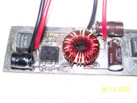
N-Channel said:all of my pcb's are hand-done, but I will take a pic of one and post it. I did a board a few years ago, and tinned it with solder, but never populated it. It was designed for an LM2596 (150kHz, 3.0A). I am at work now
I would appreciate that. thank you.
Hi guys,
Came across the thread as I am also currently designing a circuit using the LM2678-ADJ. As you chaps have expereinces building the LM 267X series, I have some queries which I hope you all can assist.
1. I notice from the datasheet that Cout determines the unity gain bandwidth of LM2678 and it is set to the norm of 40Khz. In some of the simulations I ran, some of the unity gain BW is as high as 110KHz!
2. With so much possibilities in capacitor and inductor selections, what is the "actual" stability criteria? The closest answer that I have found is that "it does not really matter what the unity gain BW is, as long as the phase margin at the unity gain point does not reached -180 degrees"
Am I right in this?
Thanks!
 Trying to shrink pic size to get under 100K size limit, ans new camera. Any ideas?
"Trying to shrink pic size to get under 100K size limit, ans new camera. Any ideas?"
http://bluefive.pair.com/
I use PIXresizer
Regards
Heinz!
http://bluefive.pair.com/
I use PIXresizer
Regards
Heinz!
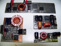
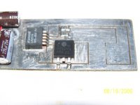
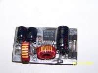
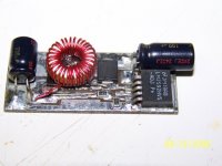
Great! Will try that later today. Sorry taking sooooooooo long! Basically, I took 5 or 6 pics of somel buck and boost regulators I did over the past years. They are based on the following chips: LM2592S-ADJ, '2596S-ADJ, '2677S-ADJ, and '2577S-ADJ. They are: 42V to 13.5V @ 3A buck, 13.5V @ 2A buck (unfinished), high-efficiency test-bed, and 12V @ 1A boost for a bike generator, respectively.
- Status
- This old topic is closed. If you want to reopen this topic, contact a moderator using the "Report Post" button.
- Home
- Amplifiers
- Power Supplies
- some questions about switcher regulator (LM267x family) from National