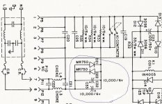
Hi AndrewT, Yes, mine doesn't quite work right. My apologies. Attached is the actual Levinson circuit. Looking at it, it looks like they are not worried about the cap being reverse biased by one diode drop. And you kids playing at home, this is seriously dangerous. Really think about the impact to the electrical grid if a bad idea or mistake happens. And think about the danger to yourself. Using a VariAC and an isolation transformer is highly recommended.
Attachments
Hi,
some manufacturers state their electros can stand upto 1.4V or so of reverse bias.
I have not seen whether this is time limited or a permanent limit.
Using one diode drop ensures that 1.4V is never exceeded provided the diode does not fail.
But most manufacturers use two diodes drops to allow smaller caps to be used.
The caps in your post add to 20mF. That pair supports a pretty big transformer working fairly hard, continuously.
Andrew,
Once again thanks for your formulas. I've been busy searching since, but got some sidetracked on stiffener caps on the DC... anyway, I also looked again at peranders' design. I don;t claim to understand it, but it looks amazingly simple (in terms of parts count), and I think I'll opt for something like that.
You are right: not being confident in designing schematics and not really knowing what is right means a tried and tested design is the best solution. Cannot argue with that.
...and sorry to bother again, but if you took my above schematic but wired the two caps in parallel across the AC lines, what would that actually do? (sorry, but it's been bugging me what I can do with the 150uf/350v caps I have, and I'm also trying to get my head around the theory..)
regards!
AndrewT said:A second problem your layout adopts is single diode voltage bypass.
The diodes may overheat in this situation. The diodes should only rarely be required to conduct, i.e. during start up or fault condition until protection triggers.
Running the diodes with repeated pulses was never intended, unless you are sure it will not cause an increased risk of failure.
How will you decide if there is increased risk of failure?
How will you test the long term reliability/safety of a prototype circuit?
Will the circuit achieve it's intended purpose, DC blocking, if the diodes repeatedly conduct?
Keeping in mind you/we are working with mains voltage, I recommend you scrap your layout and adopt a safer one.
I am afraid to say that I do not see good logic.
Actually, the caps are doing DC(small)-blocking.
The diodes just behave as shorted conductors when they see
any voltages greater than their barrier voltages (about 0.7V each).
Anyhow, I much appreciate your safety concern.
Yes, safety is the first!
")
Regards
Attachments
Hi Ssmith,
your 350V caps are much more useful than throwing them at a DC blocker.
Save them for a good purpose:-
NFB loop.
Input and output blocking for amplifiers and preamps.
Speaker crossovers.
Many others.
You need big capacitance at low voltage and polarised for Mains DC blocking. These are cheap caps that I susect have very little influence on sound quality once their prime purpose has been achieved.
10mF, 16V electrolytic of adequate ripple.
I plan to use 3m3F 16V paralleled three times for mine (9m9F) and they are dirt cheap (I bought 100 @ 10p each).
You had the right idea when you recognised the 10W per cap and 6//ed caps giving 60W but for 600W you need 60//ed caps, what a waste of resources. If you adjust the limiting voltage you can use fewer or more caps for the same wattage. I think Peranders mentions this.
Hi Bab,
you have not moved on.
Why persist with that badly designed circuit?
I can and do make mistakes. Where did my logic go wrong?
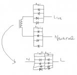
The diagrams you just posted are NOT equivalent
and you continue to follow the dubious practice of blocking both the live and neutral lines.
Did you go back and search the recent threads on DC blocking and follow the safety arguments put by both sides for the disadvantages for blocking either the live line or the neutral line?
When you read those arguments did you realise that blocking both lines incorporates the disadvantages of both schemes?
Do you want help here? Or are you trying to wind me up?
I suspect you have done little homework since you first got my attention, keep going the way you have and you will lose it.
you have not moved on.
Why persist with that badly designed circuit?
I can and do make mistakes. Where did my logic go wrong?
The diagrams you just posted are NOT equivalent
and you continue to follow the dubious practice of blocking both the live and neutral lines.
Did you go back and search the recent threads on DC blocking and follow the safety arguments put by both sides for the disadvantages for blocking either the live line or the neutral line?
When you read those arguments did you realise that blocking both lines incorporates the disadvantages of both schemes?
Do you want help here? Or are you trying to wind me up?
I suspect you have done little homework since you first got my attention, keep going the way you have and you will lose it.
Andrew,
Thank you again.
In the meantime I've been looking at the Per-Anders schematic. It's actually far more simple than I thought once I studied it properly (I have only just worked out how to read simple schematics, and this one is published in a very clear way).
Here is the site link, to save anyone who stumbles on this post from further searches.
The parts count is low. The parts are easily available and cheap. Can't think of any reason to try and do anything else.
regards,
Stefan
In the schematic you've attached, the DC blocking is after the filter. That makes no sense to me, as DC would bring the choke cores closer to saturation, woudln't it?
Also, I've been doing some simulation of DC blockers in a transformer feeding a rectifier-capacitor supply, and the capacitors I see in most schematics are far too small. For example, what is the current draw of that Levinson?
Hi,
the DC blockers are usually polar electrolytics.
This necessitates back to back, series connection of a pair.
That immediately reduces the effective capacitance by half.
The peak current bypass formed by the two inverse connected diodes should only conduct on rare non operational conditions. I suggest they should only conduct at start up and during fault conditions, not during maximum music SPL condition. Some might argue that they could conduct during maximum power testing and this is a controlled Technician operated condition.
Now let's look at normal operating condition.
With single diodes, the maximum peak voltage across the pair of capacitors must be less than the conduction corner voltage of the diode, about 600mV.
Using the normal formula F=1/2PiRC and inserting F and C you can find R, the effective impedance at mains frequency.
Then using I=V/R you can find the maximum peak current before the diodes conduct.
Putting in some real numbers.
C=10mF (one pair of 20mF back to back).
Vpk=0.6V
F=50Hz
Impedance =1/(2Pi*0.01*50)=0.318ohms
Ipk=0.6 / 0.318=1.88Apk
Irms=1.33A
maximum power (@220Vac) =293W
Big capacitors are needed!
The voltage rating could be as low as 5V but I tend to favour 16V for a margin in case the diodes are double stacked and develop a maximum of 1V across each. (three // connected 3300uF 16V are still quite compact)
Maximum power can be doubled by using four diodes in double stacked inverse connected pairs.
A ClassA amplifier will tend to need bigger capacitors than a low bias ClassAB amplifier.
The ripple rating needs to be high. Paralleling helps this.
All this and no simulator.
That is simply wrong, as neither the Mark Levinson nor the Bryston circuits posted in threads here have them in series. They both assume the limited by diodes reverse voltage is insufficient to cause a problem:AndrewT said:Hi,
the DC blockers are usually polar electrolytics.
This necessitates back to back, series connection of a pair.
Levinson blocker Bryston blocker
I do find the anti-parallel connection interesting; is the electrolytic's ESR identical in both polarizations for these low voltages? If not, why not just align the capacitors in the same direction? Seems more than a coincidence that both circuits would be this way.
Another point: in your calculations, did you take into account that a transformer feeding a rectifier-capacitor supply draws a non-sinusoidal current on its primary?
Found a reference regarding this. From a Cornell Dubilier application guide:
Not clear if this is brand-specific, but I'd guess it's not and depends on the aluminum oxide chemistry. Thus, if only two series diodes are used for each direction, it should be fine (as in the Bryston circuit).Reverse voltage
Aluminum electrolytic capacitors...can withstand reverse voltages up to 1.5 V.
I am aware of the literature published by a very few manufacturers regarding small reverse voltage tolerance.
It is generally recognised that AC waveforms should not be applied to polarised caps and good practice generally uses back to back connection as the solution, sometimes with a polarising voltage to ensure correct bias across each cap of the pair. Even the small (tens of mV) input voltages use the same technique (although arguably to reduce distortion).
Can you as a prototype builder guarantee that the caps you intend using will survive this mains applied reverse voltage duty?
Are you happy that unwitting users could be operating equipment that you have "taken a chance with" and may go wrong due to a lack of research into the consequences of this cost cutting solution?
The fact that these two manufacturers (and maybe some others) choose to apply a reverse voltage to polarised electrolytics does not make it right. That they may "get away with it" does not make my statementhave them in series. They both assume the limited by diodes reverse voltage is insufficient to cause a problem:
wrong.This necessitates back to back, series connection of a pair
It is generally recognised that AC waveforms should not be applied to polarised caps and good practice generally uses back to back connection as the solution, sometimes with a polarising voltage to ensure correct bias across each cap of the pair. Even the small (tens of mV) input voltages use the same technique (although arguably to reduce distortion).
Can you as a prototype builder guarantee that the caps you intend using will survive this mains applied reverse voltage duty?
Are you happy that unwitting users could be operating equipment that you have "taken a chance with" and may go wrong due to a lack of research into the consequences of this cost cutting solution?
I suspect that the DC is biased in one direction in each particular locality and the direction of the predominant bias is governed by the users on the grid. The reverse cap connection could be to allow for a predominance in either bias direction.why not just align the capacitors in the same direction
no, I simplified to sinusoidal (Irms) as shown in the posted calculations.did you take into account that a transformer feeding a rectifier-capacitor supply draws a non-sinusoidal current
And? Just because only a few publish it says nothing about its validity. Voltages below 1.5 are simply insufficient to electrolyze alumina. I doubt there's anything in the CDE capacitors that's different in that respect than other electrolytic manufacturers -- all use aluminum oxide dielectric.AndrewT said:I am aware of the literature published by a very few manufacturers regarding small reverse voltage tolerance.
That goes doubly so for commercial products like those of ML and Bryston!Can you as a prototype builder guarantee that the caps you intend using will survive this mains applied reverse voltage duty?
You mean, thus allowing one of the capacitors to fail? That is very unlikely, as the failure mode is by buildup of pressure by generated hydrogen. No manufacturer with a legal department would pull a stunt like that.I suspect that the DC is biased in one direction in each particular locality and the direction of the predominant bias is governed by the users on the grid. The reverse cap connection could be to allow for a predominance in either bias direction.
So the question is how to estimate it correctly for the realistic case, where it is not sinusoidal.no, I simplified to sinusoidal (Irms) as shown in the posted calculations.
Hi,
Show me why it should be so.
I don't think so.after which the diodes take over.
Show me why it should be so.
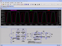
That's not at all what's under discussion you tool. Not to mention that it's not just when the AC is crossing zero, but when it's within the diode chain voltage drop around zero. But of course, we're talking about the AC across the blocker, not from live to neutral. The following simulation shows that (in this case no DC offset) the diodes only have microamp leakage current through them; the supply is drawing about 170 W; voltage waveform shown is across the blocker:classd4sure said:C'mon this is old stuff. The caps only conduct while AC is crossing zero, after which the diodes take over.
Attachments
Hi Nixie,
that comment made me go back and check your first post.
When voltage from live to neutral appears, the inductor attenuates the signal (usually spiky interference) and the caps before and after the inductor try to take the remnants to neutral and to earth. (is this the differential mode or have I got the terms interchanged?)
that comment made me go back and check your first post.
The filter uses a balanced pair of windings around the toroid inductor. The core flux caused by any DC will cancel and have no saturation effect. (is that the common mode?)the DC blocking is after the filter. That makes no sense to me, as DC would bring the choke cores closer to saturation
When voltage from live to neutral appears, the inductor attenuates the signal (usually spiky interference) and the caps before and after the inductor try to take the remnants to neutral and to earth. (is this the differential mode or have I got the terms interchanged?)
AndrewT said:Hi, I don't think so.
Show me why it should be so.
I showed just the opposite in the simulation I posted. They only conduct if a large enough voltage develops across the blocker -- either capacitors too small, or there is significant DC offset. Drawing spikes (because of the rectifier and C-input filter) of several of amps from a 120 V mains, the 2x4700 uF I simulated appears more than adequate.
Not to mention that it's not just when the AC is crossing zero, but when it's within the diode chain voltage drop around zero.
duuuh..... does it conduct or not, make up your mind
- Status
- This old topic is closed. If you want to reopen this topic, contact a moderator using the "Report Post" button.
- Home
- Amplifiers
- Power Supplies
- Powerline DC blocking and conditioning circuit