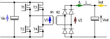
I have just started making a Full Bridge 800W SMPS for audio amps application.
Previously i have made 150W 12V to +_35V Car SMPS which is working fine since last 3- 4months.
1. I wanna know what is the power handling of Siemens EE55 & EE65 cores.
2. As per the circuit given input would be 360V and output +_35V 15A, what should be the min value of input filter Capacitor.
3. I am gonna use 25Khz Swithching Freq using 3525 & i will use 2110 for driving mosfets, Duty Cycle would be 49%, is there any need of filter Choke on output.
4. Selecting Mosfets ??? for 800W.
5. Mosfet voltage 600V .OR. 500V would suffice.
6. Mosfet driver 2110 .OR. 2113
Attachments
Good reference
You are asking very fundamental questions here! So, instead of explaining every detail I am going to recommened a book to you: "Switching Power Supply Design & Optimization ", by Sanjaya Maniktala. Very practical and to the point. A very good start. In that book you can find out how to estimate the energy handling capabilities of cores of all shapes in general, gapped and non-gapped. But, why do you want a switching (buck) regulator in the first place? Why not a simple bridge rectifier and capacitor bank? Or, if you insist on a switcher, why not a simpler flyback design? Don't forget safety: You are regulating off-line here.
Regarding mosets: You can switch mosfets in parallel, as they have a positive temperature coefficient. So, they tend to share load current evenly, as long as they are of the same type. However, be carefull with your mosfet driver, as the gate charge pump requires several amps. So, make sure your driver IC can deal with multiple mosfets. Selecting mostfets? Depends on your current requirements. The mosfet voltage needs to take in account any ringing that may occur. So, 360V plus several tens of volts for ringing. 600V would be best, but you will find that the current handling will drop proportionally with higher voltage mosfets.
You do need a filter choke, as you want to reduce the 25 kHz carrier component on the DC output. Some amplifier chips deal with just fine without it, but others don't. So, plan on using it.
See
www.smps.us
This sight has a lot of information. Some of it is very basic, and other part are quite advanced.
www.smps.us
This sight has a lot of information. Some of it is very basic, and other part are quite advanced.
800w Smps
Crissty,
Full-bridge is the best topology for 500W and above. Couple of questions:
1) Why duty cycle @49%? Are you going to PWM it, or do a buck PWM pre-regulator? The SG3525 is an excellent chip for PWM'ing the main power stage. Look at the SG3525's datasheet at ONSemi.com. Lots of good info there.
2) Is 25kHz your oscillator or switching frequency? If oscillator, I would raise that a bit to remove it far away from the audio bandwidth, say 70-100kHz for the oscillator (35-50kHz switching).
Now couple of comments: I adapted a design procedure for calculating the value of the coupling cap on tha main transformer. This cap is mandatory for all half- and full-bridges using voltage-mode PWM control to prevent the possiblilty of core saturation for uneven volts*second products on your main switching MOSFETs. My procedure is an adaptation of the procedure from George Chryssis' 1989 edition of his book, "High-Frequency Switching Power Supplies".
C(c) = (I(max) * dT) / dVC(c),
For I(max) = 1.2 I(drain),
dT = capacitor's charging time, and
dVC(c) = Coupling Capacitor Ripple Voltage
So, for a ripple voltage of, say, 30V, an I(max) if 7.5A, and a charge time of 16.67uS (60kHz), we get the following:
C(c) = (1.2*7.5A*16.67uS) / (30V) = 0.000005001F, or 5.001uF. Next standard value is 5.6uF, so use a 5.6uF rated at 250VDC.
I do have the design procedure for the input cap somewhere, and as soon as I find it, I will post it as well.
Other comment: I would stay away from flyback for any power level above 200W, simply because the drain currents will be excessively high, and the minimum required PIV ratings for your outputs will also be high.
At power levels north of 200W, almose every design uses the transformer in the bi-polar, rather than uni-polar mode, for good transformer usage.
Hope these tips help.
Cheers,
Steve
Hi Steve,
Thanks for the support,
1. I am gonna use 3525 with full duty cycle(i.e. 49%) without using Pulse width control.
2. 25Khz Switching Freq (i.e. 50Khz Osc)
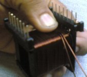
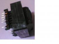
I have started with the project, as i have posted some photos of the Transformer, and am in process of completing the SMPS within a week or so.
I am concerned if the transformer E55 (no gap) handle 800-1000W, & proper input filter cap values.
Also guide me for selecting Mosfet for the same.
I will post some in process photos too shortly.
Regards,
Thanks for the support,
1. I am gonna use 3525 with full duty cycle(i.e. 49%) without using Pulse width control.
2. 25Khz Switching Freq (i.e. 50Khz Osc)
I have started with the project, as i have posted some photos of the Transformer, and am in process of completing the SMPS within a week or so.
I am concerned if the transformer E55 (no gap) handle 800-1000W, & proper input filter cap values.
Also guide me for selecting Mosfet for the same.
I will post some in process photos too shortly.
Regards,
Hi Crissty,
I agree with N-channel, that you should increase your switching frequency. The required core size will be considerably reduced with higher frequency operation. You should also think about creepage distances at this early stage. They will affect the winding window available in the transformer core.
As a guide, a recent design I worked on used an ETD49 with 6mm creepage running at 90kHz and we squeezed out 550W with fan cooling. The ETD has a similar window size and about 60% of the core material of an E55. You will probably need to look at an E65 to get to 800W.
I would also suggest you use a centre tapped transformer secondary and a 2 diode output rectifier to halve your rectifier losses.
Cheers, Ralph
Hi Crissty,
Ralphs99 and I are on the same page: Increasing your frequency will enable you to reduce the required core size, and the number of turns required for all your windings. For the wire sized you ahve selected, you should be good for about 50kHz (switching) frequency before having to worry about skin effect. All of the major manufacturers of ATX (and older AT) supplies wind their heavy-current secondaries (5V section) either bi-filar or tri-filar. I have rarely seen a quadri-filar winding. So, bumping your switching frequency up to 35kHz should be no problem.
As promised, here is the design procedure Chryssis uses for selecting the input cap. It is somewhat backwards, as it calculates the effifiency, and the I(in), first. Anyway, here it is:
P(out) = 800W, P(in) = P(out) / h, where h is your efficiency coefficient. So, say for h = 0.8 (80%) efficiency, your P(in) = 1kW.
Now, we find the input current:
I = P(in) / V(in - nominal) = 1000W / 360V = 2.778Amps.
Now we calculate the Cap's value:
C = [I x t] / DV,
where t = the charging time of the cap, 10mS for 50Hz, and 8.33mS for 60Hz, and DV is the max. desired ripple voltage.
So, for our equation, we get C = [2.778A x 0.01S] / [20V] = 0.00138888888888888F, or 1,388mF.
Therefore you should use two 680 mF, 400V caps in parallel, or any combination of 400V caps to equal roughly 20% over the rated cap value.
As for your main switching MOSFETs, I would recommend the 500V IRFP460 (I(d) = 20A). A 500V rating would give you the option of later replacing your non-PFC'ed front end with an active PFC. Of course, your caps would now want to be rated at 450V for safety.
Ralphs99 also plays it safe for his creepage distance. While almose all regualtory agencies (UL, CSA, VDE, etc.) require a minimun of 4mm for the creepage distance between the high-voltage and low-voltage sections for all circuits over 60VDC, 6mm is more preferred, again for safety's sake.
Give us your thoughts and feedback, but DO please consifer raising the switching frequency.
For your secondary, I further agree with Ralphs99 in using a center-tap winding. This way, you will be able to use the first two diodes to collect the (+) voltages and the other two diodes to collect the (-) voltages for a bi-polar (+/-) output. Ultra-fast rectifiers are OK, but if you can find some Schottkys with high enough PIV rating, I would recommend them, as they have a lower forward voltage drop.
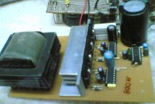
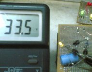
Attached image of near complete SMPS, just secondary side circuit is not made (i.e. Bridge & filter)
I tested the circuit giving input of 230V (rectified 320V DC) thru a series 200W lamp (it glows as started and goes off immediately i.e. till the cap is charged.
Very little heating on the hetsink, right now i am giving 12V regulated thru seperate transformer & 7812 to the circuit.
I have a 15V tap on trafo, i wanna know what value of startup resistace from +320V to positive voltage for circuit, so that it should be able to startup the circuit and be capable of fully charging the Mosfets properly.
Progress is little slow and steady, now to add output bridge and filter, and checking for fast bridge rectifiers @20A. I have 2-3 rectifier of old PC SMPS but it is only for +ve rectification.
Regards
Attachments
Attached image of near complete SMPS, just secondary side circuit is not made (i.e. Bridge & filter)
I tested the circuit giving input of 230V (rectified 320V DC) thru a series 200W lamp (it glows as started and goes off immediately i.e. till the cap is charged.
Very little heating on the hetsink, right now i am giving 12V regulated thru seperate transformer & 7812 to the circuit.
I have a 15V tap on trafo, i wanna know what value of startup resistace from +320V to positive voltage for circuit, so that it should be able to startup the circuit and be capable of fully charging the Mosfets properly.
Progress is little slow but steady, cause of time constaints, now to add output bridge and filter, and checking for fast bridge rectifiers @20A. I have 2-3 rectifier of old PC SMPS but it is only for +ve rectification.
Regards
Attachments

- Status
- This old topic is closed. If you want to reopen this topic, contact a moderator using the "Report Post" button.
- Home
- Amplifiers
- Power Supplies
- Wanna know about smps design