Absolutely! I had missed the point that he wanted up to 50v although that can be done using series pass devices and I know that good advice for the 317 et al to be well 'sunk' (dont realy need much though if you series pass it).
Simple analogue design using a '741' is cool in that case unless true discrete is required but then, yes, you can get complicated if you try.
A valuable dictum in these instances is: "If at first you dont succeed; Lower your standards!"
Regards, Meshuganah
Simple analogue design using a '741' is cool in that case unless true discrete is required but then, yes, you can get complicated if you try.
A valuable dictum in these instances is: "If at first you dont succeed; Lower your standards!"
Regards, Meshuganah
Another interesting approach for linear regulators with a large output voltage range is to use a switching pregulator that tries to maintain an almost constant voltage drop over the series pass transistor (or maybe just IC regulator). I first saw a schematic of such an approach over 25 years ago in a german Electronics magazine, but am not sure if I still have the schematic around (probably outdated by now anyway). I think this approach has been discussed several times on this forum too. I am not very good at switching regulators, though, so I don't know it it is possible to do a really simple such pregulator for a 317 in this case. I guess it might be possible with some of the advanced switching IC regulators on the market today.
This gives the best of the two worlds (at least in theory). The power dissipation is kept to a minimum and we still benefit from the linear regulators performance. You also wouldn't need a foldback current limiter in this case.
This gives the best of the two worlds (at least in theory). The power dissipation is kept to a minimum and we still benefit from the linear regulators performance. You also wouldn't need a foldback current limiter in this case.
") Which was a whole lot simpler and quicker.
Which was a whole lot simpler and quicker.Yes, in many cases there are simpler solutions. This schematic was intended as a high-performance lab PSU with a wide ouptut voltage range without the usual foldback current limitation at lower voltages. I found it very clever at the time, but I would guess this technique is widely used in modern lab PSUs. Large heatsinks probably cost more than a switching regulator in production.
I built a servicable dual lab supply by aping the design of a Topward bench supply. This design uses standard-issue 1458-type opamps and power darlingtons. The trick is to float a +/- supply around the ouput of the supply to power the voltageand current sensing opamps, so they follow the output voltage up and down and are perfectly happy no matter what.
Having a symmetrical supply like this also makes it easy to sense current with a standard opamp, as the output of the supply will always be within the common mode range of the opamp.
The reference is hooked up between the output and the negative output rail (a TL431 would work ffine), and you vary the output voltage by slinging a pot across the reference and appplying it to one side of the voltage sensing opamp. The other side goes to a fixed voltage divider slung between output and ground, so you have a fixed multiplier of the divided-down voltage reference.
It sounds complicated, but the whole thing fits on a surprisingly small piece of perf board. I used this power supply for years before replacing it with a real Topward bench supply, and it was rock-stable in both constant voltage and cosntant current mode.
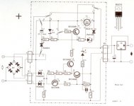
I have built an Elektor design from early 90s which does use a preregulator (see my other post in power supply design). While it works, I am etting alot of transformer noise, particularly under load. I am looking at dumping the preregulator circuit and replacing it with the dissipation limiter (works on secondary side of transformer) as described in Elektor Nov 91 (pointed out by Rick - thanks). With a few minor component changes (IRF540 in place of BUZ11) and 2N5401/4441 in place of other other transistors, this would work with voltages of 50V. Just starting to build it, so I'll let you know. Schematic attached.
Attachments
- Status
- This old topic is closed. If you want to reopen this topic, contact a moderator using the "Report Post" button.