I just thought I'd share the Soft-Power Circuit I made. Someone might find it handy and eagle files are attached so others can etch their own and change it to suit them. Its based on these two designs using a 4013 flip flop:
http://www.cpemma.co.uk/flipflop.html
http://maxhawk.flagshiphosting.com/projects/Ampturnonv2/index.htm
It basically just lets you use a nice little momentary switch to activate a relay for switching amps, preamps or whatever on and off, just like a bought one")
Mine uses a transformer from Jaycar which is exactly like an Amveco one but it is 45mm square instead of 50mm. I will be using a solid state relay.
Pics:
http://www.cpemma.co.uk/flipflop.html
http://maxhawk.flagshiphosting.com/projects/Ampturnonv2/index.htm
It basically just lets you use a nice little momentary switch to activate a relay for switching amps, preamps or whatever on and off, just like a bought one
Mine uses a transformer from Jaycar which is exactly like an Amveco one but it is 45mm square instead of 50mm. I will be using a solid state relay.
Pics:
An externally hosted image should be here but it was not working when we last tested it.
An externally hosted image should be here but it was not working when we last tested it.
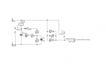
That's great, but a bit of an overkill. First, note that it can be done without the transformer if the on-off signal is allowed to be mains live. Second, the solid state relay may be replaced by a triac and triggered by a compact 8 pin microcontroller, that may also achieve other functions like phase controlled soft-start, brownout detection, frequency checking, overvoltage and undervoltage protection, emergency shutdown, etc...
That's how I would do it.
That's how I would do it.
Eva said:That's how I would do it.
Well, post up your schematic and PCB layout then

Originally posted by Eva First, note that it can be done without the transformer if the on-off signal is allowed to be mains live.
Also, one of the main motivations for using my circuit is so that you can use nice looking switches on your equipment and most of them will not take 110/220V, eg the bulgin switches:
An externally hosted image should be here but it was not working when we last tested it.
Hi Rick,
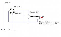
If you look at the optocoupler, its actually a Photovoltaic Driver from IRF which upon LED activation in it produces a voltage for gate drive of IGBT by the virtue of Photocells arrayed in it......
So theres no need of external supply apart from triggering the LED which could simply powered up by small rectified voltage scale down from mains AC itself.....
Have a look at this:
http://www.irf.com/product-info/datasheets/data/pvin.pdf
K a n w a r
About a year ago, I had an idea to design a board with a small PS and several 555 timer ICs. The user would trigger the PS to turn on, which would start the timers going, the first timer triggering the next, etc. On shut down, other timer ICs would reverse the shut down sequence so the whole thing would be first-on, last-off. Finally the last shutdown timer would kill the power to the onboard PS via a NO relay, so the whole thing would shut itself off. All the relays would be off-board, ice-cube type or similar, since a 10A or more is cheap and widely available. Also, the 555 timers are cheap and each time interval could be adjusted via a potentiometer.
I would use such a thing to sequentially turn on line-level electronics (e.g. crossover circuitry), then power amp, then a relay between amp and speaker, all of these in an active speaker or subwoofer. On shut down, the amp-speaker relay would first disconnect, then the power amp would shut down, and finally the line level electronics. This would eliminate turn-on and turn-off thumps. You could also use this to bypass a soft-start thermistor after a few hundred milliseconds or so.
This seems like one part of that whole idea.
-Charlie
- Status
- This old topic is closed. If you want to reopen this topic, contact a moderator using the "Report Post" button.
- Home
- Amplifiers
- Power Supplies
- My Soft-Power Circuit