I keep lookin at 'em, thinkin how to get two 40V rails for my power amp. One's easy; gettin the negative one is also easy if you have a dual-40V transformer, but what about a full-wave center-tapped design? What will happen if you tie the input of the negative one to the ground of the other, and the center tap? I don't want to let the smoke out... particularly not with what I'm paying for those 338s.
Suggestions? Cautions? I've seen Pedja Rogic's dual rail supply, nice job BTW, I saw a mention of CarlosFM's improvements but haven't managed to come across them so far, any pointers greatly appreciated.
Suggestions? Cautions? I've seen Pedja Rogic's dual rail supply, nice job BTW, I saw a mention of CarlosFM's improvements but haven't managed to come across them so far, any pointers greatly appreciated.
OK, so here's a hack at it. I'm still thinking about the bypass diode on VR2. I suspect that makes ground always more negative than the center tap. I'm also not entirely happy about the cap from the center tap to ground; it might store charge and push the center tap up.
Comments? Suggestions?
One additional note: I found a second source for the two-transformer dual output supply with two positive regulators... in the National LM340 dox, page 14. My first source was the NEC dox for their regulators, page 21, circuit 14. Both show diodes bypassing the negative to the positive output of each regulator- that is, from -V to G, and from G to +V. The NEC dox claim that if you don't put them there something can go negative during startup and really screw things up. I noticed that was missing from Pedja Rojic's design. I still haven't seen CarlosFM's.
Attachments
OK, got it.
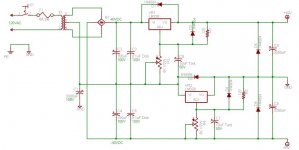
The key is to add two diodes to the center tap; one pointing from ground of the positive regulator to the center tap, and one pointing from the center tap to the positive side of the negative regulator.
A second key is to ensure that the regulators don't fall out of regulation due to light load (which will allow ripple into the load, AKA "power hum" from the quiescent amp). To do this, I've added a 1K resistor between each rail and ground. Thus, quiescent, the supply draws 40mA on each side. It can supply 5A (minus that 40mA; fine, 4.96A ) from either rail to ground, and 5A from rail to rail. D1 protects against the center tap going positive and dragging ground up, and D2 protects against Vin to the regulator from being dragged negative by the center tap should it go negative. CR1 supplies full-wave to each rail, and the negative regulator conditions the negative rail thru ADJ and the 10uF tantalum cap (which bypasses ADJ to AC ground and gives ripple rejection of 75dB).
A major factor in the design in order to get the best possible noise performance and load regulation is to ensure that the bottom of R2 is connected to ground where it enters the load, rather than on the power supply board; however, both ends of R1 must be very close to the regulator. C1 and C2 provide for sudden demands from the regulators, and C3 and C4 decouple them from the power line. C7 and C8 provide "clean" power for sudden demands from the load, and C9 and C10 again decouple the regulator (they are actually on the load board, it was using unregulated power which is why I'm doing this in the first place ). I'll probably add another pair of .1uF disks to the outputs of the regulators, just for grins, since C9 and C10 are so far away.
Finally, D3 and D4 provide a discharge path for C7 and C8, so they don't destroy the regulator at startup or if there is a line short, and D5 and D6 send the discharge from C5 and C6 to the same place, since these caps are dangerous to the regulator in the event of either load or line shorts. C1-C4 cannot damage the regulators because they are on the input sides.
Someone have a look and tell me I'm not insane, please.
The key is to add two diodes to the center tap; one pointing from ground of the positive regulator to the center tap, and one pointing from the center tap to the positive side of the negative regulator.
A second key is to ensure that the regulators don't fall out of regulation due to light load (which will allow ripple into the load, AKA "power hum" from the quiescent amp). To do this, I've added a 1K resistor between each rail and ground. Thus, quiescent, the supply draws 40mA on each side. It can supply 5A (minus that 40mA; fine, 4.96A
) from either rail to ground, and 5A from rail to rail. D1 protects against the center tap going positive and dragging ground up, and D2 protects against Vin to the regulator from being dragged negative by the center tap should it go negative. CR1 supplies full-wave to each rail, and the negative regulator conditions the negative rail thru ADJ and the 10uF tantalum cap (which bypasses ADJ to AC ground and gives ripple rejection of 75dB). A major factor in the design in order to get the best possible noise performance and load regulation is to ensure that the bottom of R2 is connected to ground where it enters the load, rather than on the power supply board; however, both ends of R1 must be very close to the regulator. C1 and C2 provide for sudden demands from the regulators, and C3 and C4 decouple them from the power line. C7 and C8 provide "clean" power for sudden demands from the load, and C9 and C10 again decouple the regulator (they are actually on the load board, it was using unregulated power which is why I'm doing this in the first place
). I'll probably add another pair of .1uF disks to the outputs of the regulators, just for grins, since C9 and C10 are so far away. Finally, D3 and D4 provide a discharge path for C7 and C8, so they don't destroy the regulator at startup or if there is a line short, and D5 and D6 send the discharge from C5 and C6 to the same place, since these caps are dangerous to the regulator in the event of either load or line shorts. C1-C4 cannot damage the regulators because they are on the input sides.
Someone have a look and tell me I'm not insane, please.
Attachments
That arrangement is inefficient in terms of diode losses and transformer usage. Furthermore, it will cause transformer saturation in case of any load imbalance between rails. A transformer with two independent secondaries is required in order to get reasonable performance.
Also, don't waste capacitors connecting them at the output of the regulator, they are required at the input for rectification instead. 100uF at the output is enough.
Also, don't waste capacitors connecting them at the output of the regulator, they are required at the input for rectification instead. 100uF at the output is enough.
Thank you for the advice.
I believe that D1 and D2 are necessary to prevent the negative regulator from browning out. Actually, it is D2 that is the main element in this regard; D1 merely preserves the symmetry of the loading from the center-tap's POV, mitigating the potential for unbalanced loading at least from the regulator components. Do you agree?
The system runs from standard US 120VAC, hot, neutral, and ground. Other than chassis heating, I am relatively uninterested in efficiency; thus, the minor inefficiencies of two 1.4V diode drops are of little concern to me in a 40V supply. Were the output voltage less, making the inefficiency greater, or were I working under extreme conditions where heating or waste of power were of great concern, I would avoid a linear regulator in the first place and ask you folks for advice on designing a SMPS; I have been working on a Cuk converter for another application for quite a while, titivating it to try to get the efficiency up in the 90th percentile (I'm an amateur astronomer, and I want extremely high efficiency DC-DC conversion to condition battery output (10A 12V) and currently it's at 87%- I may ask for advice later). In intermediate applications, I suspect your comments on efficiency should help others guide application of this supply, and I agree with them.
In regard to the output caps, they are already present on the amp board; and they present a surge current source that might keep the regulators from shutting down should the load beyond them make a sudden demand. While I could dismount them, it would be a big hassle and I have much newer technology 3300uF cans to use in the input filter. Under other circumstances, you would be absolutely correct, there is no justification for using such large output caps.
The application is a guitar amplifier, and the relevant design details are:
1. Opamps for the preamp/tone amp, and on the chorus and reverb board, powered by +/- 15V derived on the chorus board from the main +/- 40V supply; there are a few discrete transistors, serving mainly as high-gain class-A small signal amplifiers, but they are arranged to run from +/- 15V as well. I see no signs in the design of unbalanced load, and if there is any, it is on the close order of 100 milliamps, whereas the total demand is on the close order of 3A.
2. Power amp is Darlington pairs (discrete, not single-package) arranged as the main elements in a classical B-class push-pull power amplifier, with symmetrical adjustable active biasing, designed to be adjusted to place the ground of the class-B amp as close to true ground as practical. As far as I can see, the power amplifier elements are also symmetrically designed, far more so than the preamp and chorus/reverb; I see no reason to believe the power demands from the power amp will not be highly symmetrical, to within tens of milliamps or less.
The amp currently runs completely unregulated; that is, the center-tap from the transformer goes to ground, and the output of the bridge rectifier (CR1 in my schematic) goes to the two 6800uF caps at the output of my supply, and the two 0.1uF poly caps (C7-C10). That power is directly applied to the power amp without further ado. If I understand matters correctly, this presents the same potential problems with saturation that my design does; all I have done is add regulation. It's a late-'80s Ampeg SS-140C, if you're curious. And my goodness, you should see how these folks mistreated ground. But 'nuff a that, it's off-topic.
Based on this I believe that except under component failure conditions in the load or the regulator, the load will remain balanced (on average over time, that is; a pure sine wave would of course alternately demand current from one side then the other at its fundamental frequency, but the preamp design limits the bottom frequency to perhaps 40-50HZ; this is about the bottom note a guitar can make, and it is, after all, a guitar amp). I will check, by hooking the existing supply up and measuring the currents under quiescent, normal, and extreme conditions.
While I know my way around general electronics, I am not a professional; I believe that when you speak of "saturation" of the transformer, you mean that the unbalanced magnetic field will saturate and heat the core, which could damage or destroy the transformer if prolonged or extreme, but I am not certain of the details, so could you please explain in some detail so I can evaluate the risks? Also, if my understanding of the original design is correct, I believe these risks are present in that design; could you please confirm or deny?
And just for clarity, I have amended the schematic slightly; first, the exact measured voltage at the output of the rectifier has been added. With a turns ratio of 2:1, one expects 60VRMS out of the secondary, and when I measure the output of the rectifier with my Fluke 23 (which measures true RMS, at the time the meter was made it was a major selling point), I get 58.8V (indicating that my local line voltage is running a couple volts over spec just now- the diode drops, you know). Taking this RMS voltage and multiplying by pi/2 I get 94.25VP for the peak voltage of the secondary; dividing by two to get the voltage from the center tap, I get 47.12VP, and this should very closely approximate the voltage after filtering with large caps. Note that there is sufficient headroom to provide for the ~3V minimum regulator brownout, even if the mains power fluctuates down by 5% (to 44.77V). As it is, the voltage at the inputs to the regulators will be 45.72VDC, including the diode drops, and at a setpoint of 40V (which is what the amp is designed for), the drop will be 5.72V across the regulators which is well within their design specs and will cause minimal derating. It is about an additional 2-3V beyond the brownout level.
Second, I have placed a dot-dash lined box around the components I propose to add; the components outside the box are existing, with the sole exception that the center tap is directly connected to ground in the existing design.
Hopefully this will clarify things for you.
Second, I have placed a dot-dash lined box around the components I propose to add; the components outside the box are existing, with the sole exception that the center tap is directly connected to ground in the existing design.
Hopefully this will clarify things for you.
Attachments
The power amp schematic is available in the Solid State amp forum; it is worth noting that the +/-15V supply is done by a 7815/7915 pair on the chorus board, and sent also to the preamp board; this implies that the entire demand of both the preamp and chorus is under 1A for each rail, or 2A total, and more probably under 500mA. I have scrutinized things, and the demand looks very balanced, as well- certainly to within 100mA, and probably much less than that. No-load measurements show that it is balanced to within the tolerance of my meter, which is four places on the 10A setting. (I didn't dare to check it on the 300mA setting- it's a nice meter, has lasted a long time, and I'd hate to blow it up.)
If the total demand of the system exceeds the 5A on each rail that the LM338s can put out, my intention is to redesign for 10A using the opamp idea from the LM338's datasheet. I have ordered enough LM338s to do that, and for that matter to do 15A on either rail, and I have opamps on hand.
If the total demand of the system exceeds the 5A on each rail that the LM338s can put out, my intention is to redesign for 10A using the opamp idea from the LM338's datasheet. I have ordered enough LM338s to do that, and for that matter to do 15A on either rail, and I have opamps on hand.
I wish I could be of help, but I am even much less of a designer than you!
I was wondering if you might know what the amp/voltage range of this regulator circuit would be? I'm asking because I'm looking to power several LM3875's from a transformer that is at too high of a voltage to use "as-is". I have been looking for a good circuit for it.
Thanks!
Tall Shadow
I was wondering if you might know what the amp/voltage range of this regulator circuit would be? I'm asking because I'm looking to power several LM3875's from a transformer that is at too high of a voltage to use "as-is". I have been looking for a good circuit for it.
Thanks!
Tall Shadow
LM338s will handle, IIRC, up to a 32-volt (see the data sheets) differential between input and output, but not without a cost: like all 3-terminal regulators, the higher this voltage, the less current they can source.
What is the voltage (or better, the turns ratio, and what is your electical utility sending you? For example, "my transformer has a 2:1 turns ratio; I live in the US and we use 60Hz at a nominal 120Vrms.") of your transformer? And what voltage do you intend to provide to your load? Do you need positive and negative rails? Is the load "balanced" between the rails if so? How much current does it need?
If you'll answer these questions, I'll tell you if this design is useful for your purposes, and advise you on how to use it (if I think you should use it at all). And I'll show you what criteria I use to judge it, as well, so you can do it for yourself next time, as well as be comfortable with my advice.
Shredly said:LM338s will handle, IIRC, up to a 32-volt (see the data sheets) differential between input and output, but not without a cost: like all 3-terminal regulators, the higher this voltage, the less current they can source.
What is the voltage (or better, the turns ratio, and what is your electical utility sending you? For example, "my transformer has a 2:1 turns ratio; I live in the US and we use 60Hz at a nominal 120Vrms.") of your transformer?
Well, I live in the U.S., so I'm running 120vac/60hz. (nominal). I have the choice of a few transformers, and the majority of the ones that I'm finding are slightly over voltage from what I want to use....(I'd like to use +- 25v and most are +- 28v-35v). I won't know the turns ratio until I choose the transformer(s). Part of the reason I inquired was to get an idea of the Input/Output/Current ranges for this type of regulator circuit, to see what options (In transformers) is affords me the use of.
Shredly said:And what voltage do you intend to provide to your load? Do you need positive and negative rails? Is the load "balanced" between the rails if so? How much current does it need?
I'm looking at powering a total of 6 LM3578 chipamps. I'm hoping to arrange them in two or three cases. This will be for a home theater set up. The chipamps take 84v max(+-42v), and run cleaner at slightly lower voltages. Each amp needs aprox. 125va-150va for current. I was hoping to power 2-3 amps per supply.
I am also looking at using these transformers because I'm trying to do this as inexpensively as I can. Paying full price for custom/ specialty transformer(s) might make this project out of my budget range. I can afford to buy transformers on the surplus market and regulate them to fit my needs........I hope!
Shredly said:If you'll answer these questions, I'll tell you if this design is useful for your purposes, and advise you on how to use it (if I think you should use it at all). And I'll show you what criteria I use to judge it, as well, so you can do it for yourself next time, as well as be comfortable with my advice.
I hope this answera your questions....and you can help me out!!
Thanks!
Tall Shadow
This won't be a problem. You've got diode drops, regulator brownout margins, and most regulators can drop a few extra volts across themselves without major strain.Tall Shadow said:I have the choice of a few transformers, and the majority of the ones that I'm finding are slightly over voltage from what I want to use.
OK, well 120VAC RMS is 169.7VAC Peak; that's because the RMS value is 1/2^0.5xVP. That's one over root two, or about 0.707. Your "35V" transformer, then, is almost certainly a 5:1 transformer with the peak voltage quoted (which is 33.94VP).Tall Shadow said:Part of the reason I inquired was to get an idea of the Input/Output/Current ranges for this type of regulator circuit, to see what options (In transformers) is affords me the use of.
For safety's sake, I recommend that you actually measure the outputs of the transformers with a true RMS meter (easiest to find) or an oscilloscope (which will give peak and peak-to-peak values) preferably before you buy them; and be sure that you know:
1. The VA rating of the transformer, or both the voltage and the amperage ratings. VA is in watts, or volt-amperes, and if you know the voltage fraction the secondary delivers, then you will know how much current you can safely draw from it simply by dividing; on the other hand, you can also derive the VA rating by multiplying the current and voltage. Make sure you know one or the other.
2. Whether the voltage specified is peak, peak-to-peak, RMS, or average. If they don't know, then I strongly suggest testing it with a known-good meter before you buy, and that you know precisely how that meter was calibrated.
3. Is the transformer secondary center-tapped?
and finally,
4. Is the voltage rated or your measurement of it from the center tap to either leg, or between the legs?
The same transformer (or at least one with the same turns ratio) might variously be called a 24V, 34V, 12V, or 17V transformer; and some manufacturers might use 117VACRMS on the primary to calculate the secondary voltage, whereas others might use 120VACRMS, or 110VACRMS, or 115VACRMS, so you might also see 35V or 18V. And this is just one transformer!!! Unfortunately, you'll rarely get a manufacturer, much less a dealer, to tell you what the turns ratio is unless you're buying new. So that's why I say the best thing to do is measure it. Then you KNOW.
When you're measuring, it might not quite be clear to you which of the three wires on a center-tapped secondary is what. The easiest way to find out is with an ohmmeter; you'll find that the resistance from the center tap to either leg is half the resistance between the legs.
Now, before you choose, you should know that you always design a power supply backward from the load, and that every semiconductor component in a power supply drops some voltage; so you're going to wind up with a minimum transformer that's higher voltage than your desired output voltage.
OK, now let's get into the detailed designs, now that we've covered some basics.
Well, let's see here now. First, you'll need a two-rail supply, and if you go with the maximum practical 40V, you'll need 2A on each rail (conservatively- that will give you 160VA to play with, which should be more than you need). At 20V, you'd need 4A on each rail. This militates toward the LM338, with its 5A capacity.Tall Shadow said:I'm looking at powering a total of 6 LM3578 chipamps. I'm hoping to arrange them in two or three cases. This will be for a home theater set up. The chipamps take 84v max(+-42v), and run cleaner at slightly lower voltages. Each amp needs aprox. 125va-150va for current. I was hoping to power 2-3 amps per supply.
So right off the bat, you probably want LM338s with their 5A rating to ensure that you have plenty. Also, your rails will be around 20-40V. So you are definitely going to use an adjustable regulator, and in fact this also points to the LM338 which is designed for this purpose.
We have already isolated the two most important design parameters: output voltage and amperage.
Now, you're doing a linear supply because you don't want to fuss with a switcher; this will limit your efficiency, but since you will run off-line, you don't care about it really other than the fact that you have to get rid of any heat you waste.
So this means that you're doing a rectifier-cap filter-regulator design, and that's a major parameter; and it also means that we can figure out how many diode drops to add in, based on what type of transformer.
One of the limitations of the LM338 is that, unlike many other three-terminal regulators, it only comes in a positive version. This limits the design possibilities.
There are three:
1. A single center-tapped transformer, using my design here.
2. Two untapped transformers, or one dual-secondary transformer, using Pedja Rogic's design here, with one slight modification I'll tell you about.
3. Two center-tapped transformers of the needed voltage from center to one leg. The design is identical to Pedja's, with the exception that you use two diodes, one on each leg, to rectify.
For the first design, you need a 2:1 transformer, capable of delivering rather more VA than your amplifiers need; 200VA should be sufficient, and the widely-available 250VA transformer design ideal. This transformer will deliver 42VP from each leg, relative to the center tap, and is capable of sending somewhat more than 4A. If the rating is RMS, you can expect this transformer to be rated at 30V center tapped, and 10A, and likely 250 or 300VA. Brand new, this transformer is available from Digi-Key for about $50. It's Hammond 167S30. Note that this is the least expensive option. Of course, if you can find such a transformer surplus, you could save yet more simoleans.
For the second design, you would want two 30V RMS untapped transformers. These will be 4:1 transformers, and should be rated about 120-150VA, or 4-5A. You may also come across a transformer with two 30V RMS secondaries, though this is not common; it would need to deliver 4-5A for each secondary or 9-10A total.
For the third design, two 30V RMS center-tapped transformers; these will be 2:1 transformers, and should be rated at about 120-150VA or 4-5A each. This is the most efficient setup, because you can use just two diodes to rectify, which means there will be only one diode drop in each half-cycle. However, it also is probably the most expensive. You get what you pay for.
With all these options, you should be able to find SOMETHING that will fit your needs.Tall Shadow said:I am also looking at using these transformers because I'm trying to do this as inexpensively as I can.
The regulators are about $5 each. The 10uF tantalum caps are about $4 each, and the big filter caps are about $5 each too.
Consider your options, and decide what your priorities are. Let me know how you decide, and what transformers you can lay hands on; if you have trouble sourcing them, I can make some suggestions as to starting points, and I'm sure there's more info around on this site on the subject, too.
Thought about it all the way thru practice and realized that there's no way to use two positive regulators with a center-tapped transformer. Just plain flat can't be done. Like I say, it won't blow up, it just won't regulate the bottom rail. The best I could come up with was to cascade the regulators (rather than trying to mirror them, like you would for a two-transformer or two-secondary setup), but all that would do is add the same ripple to ground as is present on the negative rail. Sigh.
I'm buying a toroid from Digi-key, which has two secondary coils; normally these are placed in series or parallel, to get twice the nominal voltage or twice the current, but as long as the load is fairly balanced it should work fine as two separate secondaries, provided I buy one that gives the voltage I need in parallel and the current I need in series.
Only in this way can the DC level float properly to remove the ripple completely. The additional advantages to this in my situation are that it will leave a hole in the bottom of the amp casing where the standard transformer is now, where I can put a fan in, and it will lighten the amp. With the new higher-powered transistors, running into a 4-ohm load on each channel, and a fan, and a regulated supply, it should be relatively bullet-proof (clearly, nothing really is, but this'll come close), and very, very quiet (and the third advantage of the toroid is it makes less EMI).
Just to be clear: don't waste your time and money on my circuit diagram in this thread. It doesn't work. If you need more than 3 amps per leg and you need two rails plus ground, it appears that you should build discrete regulators, because there is no 3-terminal solution.
Well, Thanks for the effort anyway....
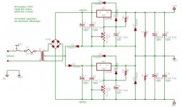
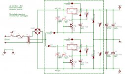
Here is something to give you some ideas...Maybe...
I know it's not exactly what we've been talking about, but it's "Food for thought".
let me know if it's any help or insperation...
Tall Shadow
Here is something to give you some ideas...Maybe...
I know it's not exactly what we've been talking about, but it's "Food for thought".
An externally hosted image should be here but it was not working when we last tested it.
let me know if it's any help or insperation...
Tall Shadow
The two secondaries in the power supply at the top is precisely what I was talking about.
While you can use an LM317 and an LM337 with that setup, you could also use two LM317s- or, more to the point, two LM338s, which would give you 5 amps on each rail, rather than the 1.5A you can get from the LM317 and LM337. Pedja Rogic's design, which I linked above, does this.
With the design you posted, you don't need two secondaries- although it does have the advantage that you don't need as balanced a load as you do with a center-tapped secondary.
You could use the centre tapped transformer with a Lm337 regulator for the negative side with a boost transistor, to give the current you want.
NPN power transistor say 2N3055.
Emitter to smoothing cap -40V
4.7 ohm resistor base to emitter.
Base connected to input of regulator.
Collector to output of regulator.
The power transistor will share the dissipation with the regulator
NPN power transistor say 2N3055.
Emitter to smoothing cap -40V
4.7 ohm resistor base to emitter.
Base connected to input of regulator.
Collector to output of regulator.
The power transistor will share the dissipation with the regulator
So it will; and current limiting is also possible. I have, however, a limited amount of space; the caps and a single TO-3 take most of it. I'd hate to try to shoehorn a TO-220 in there, and the current sense resistor that either of the two current limiting methods I know of require is completely out of the question.
And I'm a little nervous about the transformer in the first place; I don't have specs on it, and it's a nasty, heavy, noisy thing; and dangerous if it gets overloaded, IMHO. A toroid will give multiple advantages and my wife is not averse to spending the money on it.
If I recall correctly, the biasing resistor's value depends upon the DC β (AKA h(FE)) of the power transistor; 4 ohm will work fine with a 2N3055. But the current sense resistor must be able to handle all the current through the entire supply; in this case, about 5A. To forward bias the BE junction of a small-signal transistor and pull the base of the power transistor to hot to unbias ITS BE junction requires some 1-2V; at 6A (the limits of the LM338), that makes the resistor about 0.33 ohm, and 15W. Not a small resistor. You can run it unlimited if you like, but that's risky for equipment I might have on stage behind me. Nothing like a nice fire in a crowded bar. I'd be lucky to escape alive. Safety first.
I'll post a circuit with some notes shortly. Your idea is worth exploring, and it should be available if someone wants to try it.
Yes, to get current limit you put a sense resistor in the emitter lead and use it to turn on another transistor which will pull down the power transistor base.
But you only need 0.65V to turn on the transistor so 0.22ohm will give you a 3A limit thru the transistor + whatever the regulator will give.
Personally I would not bother with that arrangement I would use a fuse.
But you only need 0.65V to turn on the transistor so 0.22ohm will give you a 3A limit thru the transistor + whatever the regulator will give.
Personally I would not bother with that arrangement I would use a fuse.
- Status
- This old topic is closed. If you want to reopen this topic, contact a moderator using the "Report Post" button.
- Home
- Amplifiers
- Power Supplies
- Them dang LM338s