If you wire up 2 300VA in either of these configurations, are yuo effectively getting a 600VA transformer? Or are you getting a very expensive 150VA? Or a good way of melting copper? or are the figures incorrect and I'm getting an 80V (or a 20V) 300VA?
If this is a valid way of wiring 2 transformers, should they physically be mounted on top of each other, next to each other (flat), or some other orientation (strung from the top of the casing with organic cotton") )?
)?
The reason, of course, is money - 300VA (40-0-40) on special for $40; the cheapest 500VA (40-0-40) I can find is $86.15
Raka asked something like this in thread http://www.diyaudio.com/forums/showthread.php?threadid=60569&highlight=, but it didn't specifically answer my question - and I'm looking at an unregulated supply.
If this is a valid way of wiring 2 transformers, should they physically be mounted on top of each other, next to each other (flat), or some other orientation (strung from the top of the casing with organic cotton
)?The reason, of course, is money - 300VA (40-0-40) on special for $40; the cheapest 500VA (40-0-40) I can find is $86.15
Raka asked something like this in thread http://www.diyaudio.com/forums/showthread.php?threadid=60569&highlight=, but it didn't specifically answer my question - and I'm looking at an unregulated supply.
Attachments
The resulting VA rating from several transformers connected together is the sum of the ratings of each one as long as the resulting complex connection still involves using all the primaries at their full voltage rating (and obviously all the secondaries).
Secondary windings from different transformers can be only paralleled when the same voltage is granted to appear across them (ie: when both transformers have exactly the same turn ratios and their primaries are fed with the same voltage or when primaries are connected in series thus balancing mutually).
Secondary windings from different transformers can be only paralleled when the same voltage is granted to appear across them (ie: when both transformers have exactly the same turn ratios and their primaries are fed with the same voltage or when primaries are connected in series thus balancing mutually).
I'll probably go that way, as I was also keen to avoid 'crushing' the 2 sets of windings together anyway (if they were on top of each other). I'm not sure if there would be "magnetic bucking" (did you mis-spell that wordlndm said:AFAIK, this is valid in theory. As far as physically mounting is concerned, I would keep the xfmrs apart like any others, over the concern of inadvertent magnetic bucking.
?) with them epoxied together - but I'm open to being persuaded. I'd be able to have 2 power supplies in the one case if I could put them on top of each other - otherwise I'll have to use 2 cases (the caps are 150x75mm ea). I guess this is OK as 2U rack mounting boxes are also on special
The transformers will all be from the same batch and they'll all be being fed from the same source. Looks like I might be getting a cheap 600VA trannie (well, 4, actuallyEva said:Secondary windings from different transformers can be only paralleled when the same voltage is granted to appear across them (ie: when both transformers have exactly the same turn ratios and their primaries are fed with the same voltage or when primaries are connected in series thus balancing mutually).
).BTW, thanks for the responses. I wonder if anyone has actually done this?
m-a-g-n-e-t-i-c, no I think that's how it's spelledCloth Ears said:"magnetic bucking" (did you mis-spell that word

The transformers only need to be connected electrically to do what you want. Magnetic interference will only hinder them. When mounting them together (which ordinarily I would never recommend), the results wouln't be that predictable.
I routinely use the secondaries of small transformers scrapped from other equipment connected in series-parallel (with primaries in parallel) in order to obtain a low-cost isolated 230V mains source for SMPS work. Note that winding polarity matters.
BTW: You can mount several power toroids in any way you want, stray magnetic fields are low enough to yield any mutual interaction negligible. That does not apply for SMPS transformers, tube output transformers or signal transformers, though.
BTW: You can mount several power toroids in any way you want, stray magnetic fields are low enough to yield any mutual interaction negligible. That does not apply for SMPS transformers, tube output transformers or signal transformers, though.
lndm said:m-a-g-n-e-t-i-c,

I can theoretically fit 2 amp boards, 2 soft-start circuits, 4 trannies and filter caps in a 2U rack mount box, with a bit of space to spare. The trannies won't fit on top of each other anyway (114mm), so I won't worriy about that. I'll just get the bits home and see if they fit 'properly'. It doesn't matter if I have to get another couple of cases to get them to fit 'nicely' (and it makes them easier to work in).Eva said:BTW: You can mount several power toroids in any way you want, stray magnetic fields are low enough to yield any mutual interaction negligible. That does not apply for SMPS transformers, tube output transformers or signal transformers, though.
Gee, that was an easy decision - monoblocks
!Paralleing transformer shall consider that the transformer are have identically characteristic, such as voltage level, phase error angle, polarity, etc.
For big (utility power company) they must consider harmonics when energizing parallel Transformer. For small transformer like amps power supply, I have no problem experience so far. On text book the primary cable shall have same length, but it may neglected anyway.
When we have no problem then we got 300VA+300VA=600VA
From the picture in the first post, 40V outputs go to bridge rectifier, 0V to ground.kartino said:Add: the safest way is connected the DC output, ie, both transformer rectified.
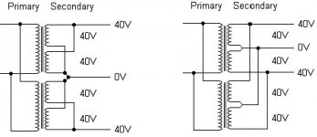
Any preference in wiring on secondary side (picture on left or right)? Or are both the same?
Thanks for post
kartino said:As long as both transformer are equal each other, both are same.
Except the one on the right is more simple. All coloured wires from one join the same coloured wires from the other. The one on the left is more like weaving
.Thank you
It shouldn't matter - both configurations are perfectly acceptable. If they can do it with 3 phase 10+MW transformers (as is routinely done), it should be pretty trivial to do it with off the shelf identical transformers!
If the transformers are slightly different (say different brands) then it should still be possible to parallel them, except they will have different winding impedances, and thus current sharing will not be equal. Slight differences in voltage (a percent or two) also give rise to this (but there is no short circuit type current or anything like that, provided the windings are connected in-phase that is!).
I say go for it. I have seen amps with parallel transformers before, and they worked no problems.
Chris.
PS: I assume the transformers you are talking about are the ones from Altronics!
real said:PS: I assume the transformers you are talking about are the ones from Altronics!
The Springvale shop should have 8 less shortly (plus they should be missing a couple of 2U rack boxes
)!Hi,
the diagram on the left is better if the transformers are 0,40 - 0,40.
Reason being that the secondary windings will almost certainly be bi-filar wound thus ensuring an exact match for number of turns and length of wire.
If the transformers are 40,0,40 then you can only wire them up using the diagram on the right (no choice) and you cannot guarantee that the windings are identical. However if you rectify each winding separately and then parallel them, you help with the current sharing in the winding and through the bridge.
The secondary winding will have a small resistance and even if there is a small (one turn) difference then the winding resistance will help towards current sharing.
AndrewT said:If the transformers are 40,0,40 then you can only wire them up using the diagram on the right (no choice) and you cannot guarantee that the windings are identical. However if you rectify each winding separately and then parallel them, you help with the current sharing in the winding and through the bridge.
I believe this is the case (I haven't been there to buy them yet). This is the link to the item I'm looking at (http://www.altronics.com.au/index.asp?area=item&id=MB5540) - it's indicated as "40 + 40", and also has additional 15 + 15V secondary windings. I believe this to be 40-0-40, but I haven't got them yet. I can grill the manufacturer later...
How would you "rectify each winding separately and them parallel them"? Are we talking 2 BR's or 4?
Hi,
if the transformers turn out to be 40,0,40 then only one bridge per transformer is required. This will be a slight upgrade of the diagram on the right.
You can modify the transformer to convert it to a 0,40 & 0,40. Do want instructions?
For a 0,40 & 0,40 you need a bridge for each winding, if you want to parallel the individual windings. It's small extra cost but ensures better matching (sharing).
I'll buy them first and then come back to this thread.AndrewT said:Hi,
if the transformers turn out to be 40,0,40 then only one bridge per transformer is required. This will be a slight upgrade of the diagram on the right.
Yes (re: the instructions)... but only when I'm sure of the transformer layout anyway. It looks like if they are 40-0-40 then the set-up is simpler (one extra bridge per channel), and with the 0,40 & 0,40 then you get better matching for an extra 3 bridges per channel.You can modify the transformer to convert it to a 0,40 & 0,40. Do want instructions?
For a 0,40 & 0,40 you need a bridge for each winding, if you want to parallel the individual windings. It's small extra cost but ensures better matching (sharing).
In either case, it looks like I can get my 600VA transformer for about half the normal cost. And I'll be learning something as I go. But buying the items comes first...
- Status
- This old topic is closed. If you want to reopen this topic, contact a moderator using the "Report Post" button.
- Home
- Amplifiers
- Power Supplies
- Does 300VA + 300VA = 600VA?