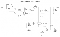
I'll guess you have pretty many opamps to choose from and NE5534 is not so bad. You should look for speed around 10-20 V/µs. If you want to choose faster opamps you may check the "super regulator" which has a class driver for the pass transistor.
What are you going to use the regulator for?
What are you going to use the regulator for?
I want only make test in phono preamp, line preamp and my analog circuit cd player because i use 78XX. As i wrote i have 32V. unreg. for PS phono and line preamp but i have 24V. reg for my 2 circuits. My PCB for this PS circuit is already design. I think used the AD817/DIP8. Can i use it this opamp?thank you!!
maxpou said:I want only make test in phono preamp, line preamp and my analog circuit cd player because i use 78XX. As i wrote i have 32V. unreg. for PS phono and line preamp but i have 24V. reg for my 2 circuits. My PCB for this PS circuit is already design. I think used the AD817/DIP8. Can i use it this opamp?thank you!!
If you supply the opamp from the regulated output voltage rather than the unregulated input voltage, the improvement is more than you can do with any opamp swap - and is basically free.
You really should read the super reg threads.
Jan Didden
janneman said:If you supply the opamp from the regulated output voltage rather than the unregulated input voltage, the improvement is more than you can do with any opamp swap - and is basically free.
You really should read the super reg threads.
Jan Didden
It's no improvement at all IMHO.
All those super-duper high-speed opamps is asking for trouble.

:bs:
The thing is that only some opamps will start if you do that unless you add some "trick", one of them can be found in the mentioned threads.janneman said:If you supply the opamp from the regulated output voltage rather than the unregulated input voltage, the improvement is more than you can do with any opamp swap - and is basically free.
You really should read the super reg threads.
I'll guess you are right for _some_ applications but have you really tried?Elso Kwak said:It's no improvement at all IMHO.
All those super-duper high-speed opamps is asking for trouble.
peranders said:
I'll guess you are right for _some_ applications but have you really tried?
YEP
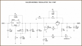
In that schematic, the LM317 is set up to force the pass transistor to work at a fixed Vce of 1.25*(1000+825)/1000=2.28V. You can imagine it as an "active cascode". Knowing bipolar transistor behaviour at low Vce levels, I don't think that such a low Vce can provide any advantage, 5V would seem more reasonable.
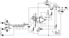
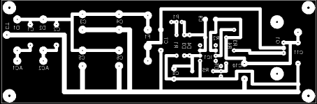
hi, i send you the schematic and pcb with the modification for supply of IC1. please i would to know if it's correct or i can have problem.
IC1:AD817
D1,D2: BY255
C1,C2,C7,C11: WIMA MKP10 .01
C3,C4,C5,C6: NICHICON FW 4700UF
Q1: D44H11
C8,C9: 47UF ELNA CERAFINE
C10: 100UF ELNA CERAFINE
D3,D4: 1N4148
D5: LM329
I TRY LM317 AS JUNG LATER
IC1:AD817
D1,D2: BY255
C1,C2,C7,C11: WIMA MKP10 .01
C3,C4,C5,C6: NICHICON FW 4700UF
Q1: D44H11
C8,C9: 47UF ELNA CERAFINE
C10: 100UF ELNA CERAFINE
D3,D4: 1N4148
D5: LM329
I TRY LM317 AS JUNG LATER
Attachments
Elso Kwak said:
It's no improvement at all IMHO.
All those super-duper high-speed opamps is asking for trouble.
:bs:
That fateful phrase from Audio Amateur "It oscillates, now what" --
- Status
- This old topic is closed. If you want to reopen this topic, contact a moderator using the "Report Post" button.
- Home
- Amplifiers
- Power Supplies
- power supply sulzer-borbely