
arnoldc said:Darn, I simulated this thing with LTSpice and it should give me around 200V.
Grrrr.
So it should. However here is a list of possible problems:
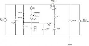
1) The gate of the MOSFET needs protection - a 10-15V zener between gate and source, otherwise the MOSFET could easily be broken - resulting in a high gate current and an additional voltage drop on 1M resistor.
2) 47uF capacitor could be leaky, again reducing the output voltage.
3) 1mA current through the zeners may be not sufficient for a particular zener type you are using.
Check DC voltages on each capacitor and it will be clear where exactly you lose the voltage.
Cheers
Alex
P.S. - perhaps it would be reasonable to add a protection diode (i.e. 1N4004) across the current source transistor in reverse polarity and a series resistor to the drain of the MOSFET to reduce the dissipation and protect at least a bit against short circuits and overloads.
Eva, you're absolutely right!
Last night I was making measurements to check against the simulation on LTSpice (attached).
I noticed that the simulation says I should get ~200V after 1M (Node7 on model), but I'm getting only 100V or so.
So I was wondering why it is so.
Does that mean I have a crappy 47uF capacitor? I actually changed it to another one- 100uF and got the same results- 100V.
Attachments
arnoldc said:It's bad MOSFET
Thanks to Eva and Alex!
Don't forget to put a 10-15V zener between the gate and the source for a replacement MOSFET - otherwise you'll end up with two bad MOSFETs... also could be useful to reduce the capacitor value on the gate down to 10-22 uF and the resistor value from 1 Meg down to 100K. The time constant on the gate is too large.
Alex
Hi,
leakage on both electros are a problem.
You only have 1.1mA flowing through your current source.
This gives about 56mW on each Zener. It's better to bias them with 10% (or more) of rated capacity (about 100mW).
Then allow for leakage in the caps and add these together to find the Current Source requirement.
You've got a little capacitance multiplier in there.
While the input voltage varies from your set point the FET is dissipating all the spare energy. Particularly at start up.
As Eva & Xpro said:- lower your time constant.
Hi,
once you have the modification done, go and measure the volts drop across the 100k.
It will give you the leakage.
I then suggest you consider reducing the 560r slightly to increase the Zener current, about 270r to 330r should be about right.
This will raise your output voltage very slightly, but more importantly will allow small variations in leakage current to have less effect on the Zener voltage due to it's being biased more heavily.
arnoldc said:Hi Alex and Andrew, thanks for the replies.
Unfortunately, you're talking to a newbie here who only uses Duncan PSUD to make PSU
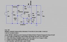
The protection diode's direction is positive to the gate?
I will change to 100K and 10uF to change the time constant.
Here is the updated schematics for you:
Cheers
Alex
Attachments
Hi Andrew,
changed to 100K and 10uF, I get 2.4V across 100K.
changed 560R to 280R (560R ||) and got 2.2V across 100K, with a slightly higher voltage- 218.3V vs 212.4V
does that look right?
Hi Alex,
thank you for the updated schematic. I'll give it a try. I've seen a schematic with the zener on the mosfet the way you described it, but for a power amp (I think Rod Elliot's site). Is the protection scheme the same?
Most schematic (series pass) do not have that, but rather have an inverted 1N4007 between Drain and Source, but I suppose the IRF840 already have that internally.
Hi,
these numbers look OK.
I am surprised that each Zener gave an extra 1.2V by increasing the bias, but it confirms that they were underbiased. As a short term test:- try paralleling a third 560r to see what effect it has on Zener voltage. I would expect the increase to be less than 0.5V per Zener.
I am slightly perplexed by the lower leakage through the 100k
these numbers look OK.
changed 560R to 280R (560R ||) and got 2.2V across 100K, with a slightly higher voltage- 218.3V vs 212.4V
I am surprised that each Zener gave an extra 1.2V by increasing the bias, but it confirms that they were underbiased. As a short term test:- try paralleling a third 560r to see what effect it has on Zener voltage. I would expect the increase to be less than 0.5V per Zener.
I am slightly perplexed by the lower leakage through the 100k
.got 2.2V across 100K cf. 2.4V across 100K

- Status
- This old topic is closed. If you want to reopen this topic, contact a moderator using the "Report Post" button.
- Home
- Amplifiers
- Power Supplies
- Why is my MOSFET dropping so much voltage?