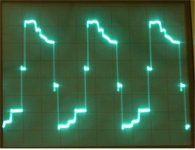
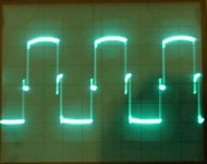
Well I thought to start of with a basic smps I would make one that could take 12(13.8)v and make +-15V @100mA. I get the required voltage at no load drawing 107mA from my psu and the output device start to get warm. So I did a bit of poking with the scope and get this as an output (see picture 1). Now if I put a snubber on the primary of the transformer I get (see picture 2) and the supply draw over 200mA of current and the output devices get very hot. 
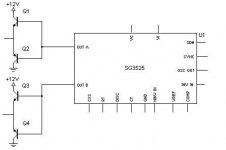
I'm using Mr. Rod Elliott's desgin but added a pair of transistors in between the pwm and transformer.
Please any idea's can really help me.
P.S pwm is running at 54KHz and tranny is old driver trasnformer from PC power supply.
I'm using Mr. Rod Elliott's desgin but added a pair of transistors in between the pwm and transformer.
Please any idea's can really help me.
P.S pwm is running at 54KHz and tranny is old driver trasnformer from PC power supply.
Attachments
Here's the switching transistors, the emitters go to the legs of the transformer.
As for the transformer, it was a pre-built one I pulled out of an old PC power supply, it was the driver transformer. I used it because it gave me 30VP-P which in a half bridge design gives a nice +-15V and I am asumming because it's a pre-built transformer I wouldn't have to worry about lage peaks from poor winding.
As for the transformer, it was a pre-built one I pulled out of an old PC power supply, it was the driver transformer. I used it because it gave me 30VP-P which in a half bridge design gives a nice +-15V and I am asumming because it's a pre-built transformer I wouldn't have to worry about lage peaks from poor winding.
Attachments
If the transformer is the classic one with two 70T windings in one side and two 10T plus another 2T in the other side, it's probably not going to suit your needs.
The transformer is probably saturating. Place a 100 ohm resistor in series with the winding you are using as primary and check the waveforms again. Then try 10 ohm. It would be useful if you could post these waveforms also.
The transformer is probably saturating. Place a 100 ohm resistor in series with the winding you are using as primary and check the waveforms again. Then try 10 ohm. It would be useful if you could post these waveforms also.
Well I tried putting the 100 Ohm resistor in the primary but it didn't change anything . The file contains the pictures of the waveform, input 1 and output one are one channel and input 2 and output 2 are another. main output is the secondary and just for you Mr. Eva I took a picture of the transformer
Here's the pictures.
. The file contains the pictures of the waveform, input 1 and output one are one channel and input 2 and output 2 are another. main output is the secondary and just for you Mr. Eva I took a picture of the transformerHere's the pictures.
Well, it looks like the magnetizing inductance of the transformer is in the low side and is playing games with the 1V deadband introduced by both your buffers and the buffers inside the IC. There are a total of four deadbands, that's why the output looks so full of stairs.
Also, the transformer is not saturating as the 100 ohm resistor would have changed things a lot otherwise, so remove that resistor. However, I recommend placing a non-polar 1uF capacitor in series with the primary winding just to be sure that saturation is not possible.
Try to place a load in the secondary side, either a single resistor directly across transformer terminals, or one resistor across each rectified ouput. Try to draw something like 50mA or +-25mA respectively. The waveforms should look much better with load as the interaction between magnetizing inductance and buffer voltage deadbands should be tamed.
Also, I recommend driving the transformer directly from the IC if your output current requirements are not too high. That would produce cleaner and higher output as two of the deadbands would be removed. According to the datasheet, the IC should be capable of providing 150mA reliably (something like +-50mA translated to the output).
ifrythings said:Now if I put a snubber on the primary of the transformer I get (see picture 2) and the supply draw over 200mA of current and the output devices get very hot.
What component values you used for snubber? Sounds like they are far away from optimal.
Well I tried to run the transformer off of the IC but it made a nice  audible sound and drawed over 600mA with no load (still), I put the 100 ohm resistor in series with it and made it stablize a bit (no more audible sounds) but it was still drawing a fairly high current.
I decieded to dismantal the transformer to see how it was wound, but as most pre-built transformers are glued, I broke the ferrite  but I did check out the windings and it was one layer of windings for the secondary and two for the primary.(I also found out I had it backward, as the secondary was wound first)
so anyways I have another transformer I was able to get a part (by the way anyone know of a good way to dismantal pre-built transformers) so I was woundering how to wind it?
F is 54KHz, input is 12(13.8)V, output should be +-15V@100mA
should I wind it as 10 wraps for the primary, then 25 for the secondary and then another 10 on top in series for the primary.
audible sound and drawed over 600mA with no load (still), I put the 100 ohm resistor in series with it and made it stablize a bit (no more audible sounds) but it was still drawing a fairly high current.I decieded to dismantal the transformer to see how it was wound, but as most pre-built transformers are glued, I broke the ferrite
but I did check out the windings and it was one layer of windings for the secondary and two for the primary.(I also found out I had it backward, as the secondary was wound first) so anyways I have another transformer I was able to get a part (by the way anyone know of a good way to dismantal pre-built transformers) so I was woundering how to wind it?
F is 54KHz, input is 12(13.8)V, output should be +-15V@100mA
should I wind it as 10 wraps for the primary, then 25 for the secondary and then another 10 on top in series for the primary.
ifrythings said:by the way anyone know of a good way to dismantal pre-built transformers?
Heat in electrical oven at 150-200 celsius for something like 15 mins. Hot plate of stove can be used also but you need to be more carefull not to heat core too fast as it will cause fractures.
Pry apart with "oven mittens" in hand, sometimes _small_ extra force with chopstick/screwdriver is also required. Works 9 cases out of 10.
You have to determine how many turns are needed to drive the transformer at your voltage and frequency without saturating it. If you could tell us the cross-sectional area of the center leg of the core, we can made an estimation.
Also, did you try the series 1uF capacitor as I recommended? The transformer will be very likely to saturate and cause high currents to flow without that capacitor, no matter if Rod's schematic doesn't show it.
BTW: I'm not Mr but Ms.
Also, did you try the series 1uF capacitor as I recommended? The transformer will be very likely to saturate and cause high currents to flow without that capacitor, no matter if Rod's schematic doesn't show it.
BTW: I'm not Mr but Ms.
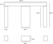
Then cross-sectional area is S=6*6=36mm^2=0.000036m^2
Peak flux for your full bridge symmetrical converter would be:
B=V*(0.25/F)/(N*S)
Solving for N:
N=V*(0.25/F)/(B*S)
Taking worst case values...
V=15V (assuming an automotive application)
F=54Khz (you are using a 108Khz clock, aren't you?)
B=100mT (reasonable level for most core materials)
N=16*(0.25/54000)/(0.1*0.000036)=19.3 turns
So your 20 turn figure for the primary was right (as long as you use a 108Khz oscillator).
Holly crap, you sure know your stuff...
F=54Khz per switching device or 108 clock is what I'm running so I think those windings will work.
thanks for your input, when I get home I shall try that and post back.
BTW you know of any website that explain how average current monitoring works? I would really like to study it.
Thanks David
If you mean average current mode control of SMPS, check that paper: http://www.powerdesigners.com/InfoWeb/design_center/Appnotes_Archive/u140.pdf
Remember to add the 1uF non-polar capacitor in series with the primary and to add some load to the secondaries (~25mA).
Remember to add the 1uF non-polar capacitor in series with the primary and to add some load to the secondaries (~25mA).
- Status
- This old topic is closed. If you want to reopen this topic, contact a moderator using the "Report Post" button.
- Home
- Amplifiers
- Power Supplies
- Funny waveform!