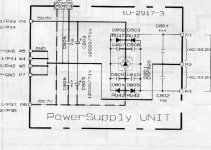
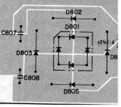
My denon has a bridge within a bridge as you can see by the schematic.
The ru4z's which are the diodes forming the bridge rectifier mounted on the pcb have been replaced with cree 600v 6A.
I am concerned about the fact that there is a Packaged bridge rectifier center tapped inside of the bridge formed by what were the ru4z's?
The circuit is exactly that from the parts list to the schematic and is verified by physical inspection.
What is to be gained from having a bridge within a bridge?
am I going to blow this baby up if I pull the packaged BR from the center and leave the bridge of cree's inplace?
The amp is a Denon PMA-2000r Each of the two mains trannies has a 5A fuse and ther is a 10 A mains fuse nameplate voltage/amperage is 120v 6A consumption.
I bounced this past my friend at AK echowars and he said that this would be the best place to post an inquiry as he hadn't seen a psu like this before.
Can anyone help me?
Attachments
The only possible explanation I can come up with is economic, why they didn't just use larger diodes escapes me. I am not sure how well the discrete diodes would share current with the existing bridge, but I assume that the forward drop of one device might be somewhat lower at low currents, and the other somewhat lower at high currents. This is only conjecture though..
You should be able to safely remove the bridge provided that your new rectifiers can handle the maximum load current on their own. It may be the case that if the Cree's have a significantly lower Vf effectively the bridge is already out of the circuit.
edit: add thought, fix typo
You should be able to safely remove the bridge provided that your new rectifiers can handle the maximum load current on their own. It may be the case that if the Cree's have a significantly lower Vf effectively the bridge is already out of the circuit.
edit: add thought, fix typo

I am not certain exactly how I should go about sizing the replacements as ther are two devices sharing in the factory design.
I just got the 600V 6A cree's thinking that the bridge was single and comprised only out of the ru4z's which are rated at 200v 3.5A each.
I wan't planning on the D5FB20 package bridge.
Which is rated at 200v5A.
I don't know if I should say that the PMA-2000 is an "Ultra High Current" amplifer.
The replacement cree at 6A with a repetative surge of 30A and non-repetative of 210A I would think should be enough but I am not so hot at PS theory.
I also have an ixys 600v27A Pre-package that I could use but would prefer the cree's as thy're already in circuit.
How do I determine if the amperage sustainable by the cree's is sufficient?
Thanks for the advice,
Tal
BTW the cree's say they are approved to parallel another "device" But I don't know if that is meant to state another cree device or any other device?
May be for redundancy, but in the case of a diode short, this wouldn't help. Not a reliable way to share current either. Recovery spikes? may be affected? Probably should remove all diodes and do it right with just the usual bridge. But - sometimes problems are fixed in totally unexpected ways. Must make sense to the designer... I would only change it if you know what you're doing.
- Status
- This old topic is closed. If you want to reopen this topic, contact a moderator using the "Report Post" button.