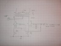
I am trying to design a current mode controlled SMPS to transform 12V from a car battery to +-45V at a maximum approx 400W power. To accomodate the current sensing, I want to use sensing transformers in the primary side. My concern is how to design the current sensing while avoiding walking the sense transformers into saturation, is this done properly in my attached drawing? Is there any other, better way of doing this?
Second, how will this control scheme work when I have no load attached, this is a scenario that might happen.
Second, how will this control scheme work when I have no load attached, this is a scenario that might happen.
Attachments
For DC, you can use a LEM hall effect current sense device.
http://www.lem.com/
You have to make a signal conditioning circuit for it, but that is not terribly difficult. In this current range, these devices are not that expensive.
The other way to do it, is to pick the current feedback signal off of the current sense/source resistor of the main switching fet. There should be a pin on the controller chip that this signal ties to.
testlab said:The other way to do it, is to pick the current feedback signal off of the current sense/source resistor of the main switching fet. There should be a pin on the controller chip that this signal ties to. [/B]
I dont want to use sense resistors because of the high currents involved, second this design will be based on surplus IRF540:s with no sense outputs along with my surplus magnetic cores, so I think current transformers are my only option (obtaining anything from the other side of the ocean is out of my price range, I prefer to learn the proper way with transformers instead)
Then what you are going to have to do, is run a wire in series with each of the fet's, through the transformer. This is your primary. The secondary of the transformer then needs to have a small load resistance, about 100 ohms or so. The signal then has to be FWB rectified and filtered. The resulting DC signal is sent into an opamp, where the gain is scaled, to accomodate the input range of the current feedback pin of your controller.
You will also probably need to have an output voltage feedback signal, isolated by an opto-coupler.
I just went through design like this at work. It can be very touchy.
You will also probably need to have an output voltage feedback signal, isolated by an opto-coupler.
I just went through design like this at work. It can be very touchy.
testlab said:Then what you are going to have to do, is run a wire in series with each of the fet's, through the transformer. This is your primary. The secondary of the transformer then needs to have a small load resistance, about 100 ohms or so. The signal then has to be FWB rectified and filtered. The resulting DC signal is sent into an opamp, where the gain is scaled, to accomodate the input range of the current feedback pin of your controller.
You will also probably need to have an output voltage feedback signal, isolated by an opto-coupler.
I just went through design like this at work. It can be very touchy.
Yeah thats pretty much the design I have in mind. What does FWB rectification mean?
Do you use one sense transformer per FET leg as in my attached schematic or do you let them share one? How do you reset the flux in the sense transformers?
I assume the transformers will reset themselves through the Rs resistor across the secondary, but I would really like to avoid having them before the diode to get rid of the diode voltage drop.
Do you have any experience regarding how many mF the capacitors on the secondary side can become without running into strange problems with feedback? I want as large as possible to avoid PSU bus pumping when feeding a switchmode amplifier.
FWB=full wave bridge. This is for making a DC control signal that has a range of 0-4 volts.
As for the output capacitance, it is really going to depend on the amount of inrush current the primary can tolerate, You can put in an inrush current limiter of some kind.
Try looking through here for more ideas http://focus.ti.com/analog/docs/techdocs.tsp?contentType=8&familyId=662&navSection=app_notes
. Most of these ideas are for the ex-Unitrode chips that are used extensively in aerospace. Look at the National Semiconductor and Linear Technology websites as well. Linear Tech has an excellent circuit designer program available for $0.
Your schematic shows the current sense transformers connected in the right way.
The key for a current sense to work properly is to avoid saturation even in worst case conditions. Saturation is caused by a too high volts*pulse_time/turns product like in any other transformer, so optimum performance is achieved by choosing the right amount of secondary turns and the proper load resistance depending on the primary currents involved. In other words, excessive secondary voltage during too much time is what causes saturation. The following formula allows to calculate the magnetic flux excursion in the transformer produced by a pulse:
B = (V/N) * T / S
Where B is flux in Teslas, T is pulse time is in seconds, S is core cross-sectional area in square meters, V is secondary voltage and N is secondary turn count.
Assuming a single primary turn, secondary voltage V in your circuit would be 0.7V (diode drop) plus (I_primary/N)*R_load. So we can substitute in the previous formula:
B = (0.7+(I/N)*R)/N * T / S
You have to estimate suitable B, I, T and S worst-case values first. Then you can just play with R and N since both are closely related.
Concerning output-filter capacitors, the value by itself DOES NOT MATTER AT ALL, as it has to be considered in conjunction with inductor parameters. You have to design a second-order output filter, modelling inductor value and its DC resistance, and also capacitor value and its ESR. The filter should produce as little peaking as possible (<6dB) and should have a low enough cutoff frequency so that the response is down by 40dB or so at the switching frequency.
Finally, frequency compensation for voltage mode control is achieved by adding a zero to the error amplifier around the frequency where the output filter has its first pole. Your SMPS will oscillate randomly and will show clumsy transient response if you don't follow that design procedure. The maximum gain value allowed above the zero has to be found empirically.
Hi,
sometimes a little different configuration is used for the current sense transformer. The idea is to saturate transformer in reverse direction, so when needed, double flux density can be used. See atached schematic. Second, when calculating volt second product, do not forget to add voltage drop of the secondary winding resistance. It is not insignificant due to the thin wire used (typically 0.1-0.15mm magnet wire).
Best regards,
Jaka Racman
Attachments
Among other things, the following thread shows an interesting current-sense transformer connection involving cascode transistors, whose purpose is to force the secondary to operate at 0.7 Volts despite the current level. The result is a dramatical reduction of current-transformer size while improving precision and signal to noise ratio.
http://www.diyaudio.com/forums/showthread.php?postid=730490#post730490
http://www.diyaudio.com/forums/showthread.php?postid=730490#post730490
Hi Eva,
i looked at at the thread but could not find particular schematic. I guess it must be something like this? I have completly forgot it, it must be 20 years since I last used it. Works quite well, since it allows easy ramp compensation for peak mode control. I first saw it in an article by S. Cuk.
Best regards,
Jaka Racman
Attachments
With this cascode scheme, how do you compensate against the variation in h_fe amongst bipolar transistors or their strong temperature behaviour? I guess a interval 40->200 in hfe for the cascode transistors will mean a factor of 5 in uncertainty in the peak current measurements.
Lossless Current-Sensing circuit
Z-
There is a really good lossless curreent-sensing circuit that senses the Vds drop across the IRF540s. This circuit came from the MP3.com blogsite. The discussion there was how to get a 12V SMPS that was powering an ITX motherboard to survive engine cranking w/o resetting the CPU. The circuit the author used was a coupled-inductor SEPIC circuit, using a UC3843BN as the PWM controller. The main MOSFET was the same IRF540 you're using, and he used this lossless current-sensing ckt for the '3843's Is Input.
I will try to look for the link and post it as soon as I do.
Regards.
Steve
Hi Zilog,
if by cascode connection you mean the circuit that I posted, then hfe is no problem. Transistor is connected in common base configuration with current gain close to 1. Emitor and collector current are almost the same, the difference being the base current which is 1/40 to 1/200 of the collector current.
Best regards,
Jaka Racman
Zilog:
All my BD140 showed a hFE of approx 200, it's the typical value for that device. This will cause a current error of -0.5% and even if it dropped to 50, the current error would be still -2%.
Note that this is far more precise than any +/- 5% current sense resistor, and outperforms any system based in Vds-on measurement, as these easily show +/-20% errors.
Jaka:
This is the cascode-transistor schematic, the same that you showed:
And this picture shows the two small current transformers:
They are indeed small, if we consider that they are sensing currents in excess of 15A with a 100:1 ratio and producing a gentle 1V/A noise-free output signal at 32Khz (actually they won't saturate until 16Khz or so).
All my BD140 showed a hFE of approx 200, it's the typical value for that device. This will cause a current error of -0.5% and even if it dropped to 50, the current error would be still -2%.
Note that this is far more precise than any +/- 5% current sense resistor, and outperforms any system based in Vds-on measurement, as these easily show +/-20% errors.
Jaka:
This is the cascode-transistor schematic, the same that you showed:
An externally hosted image should be here but it was not working when we last tested it.
And this picture shows the two small current transformers:
An externally hosted image should be here but it was not working when we last tested it.
They are indeed small, if we consider that they are sensing currents in excess of 15A with a 100:1 ratio and producing a gentle 1V/A noise-free output signal at 32Khz (actually they won't saturate until 16Khz or so).
Missing Link
Z-
Here's the link for lossless current-sensing I promised.
http://www.bobblick.com/techref/projects/mp3book/mp3book2/mp3book2.html
Hope this helps
Steve
Z-
Here's the link for lossless current-sensing I promised.
http://www.bobblick.com/techref/projects/mp3book/mp3book2/mp3book2.html
Hope this helps
Steve
I like the connection of the small transistor, because it enters deep saturation during the period in which the main switch is off, so it takes one or tro microseconds to turn-off when the main switch is turned back on, thus providing leading edge blanking.
The main problem with that technique is that the Rds-on value is dependent on temperature and on Vgs, so in practice the error is quite high when it comes to put a precise current limit or to get a precise current reading. Also, in peak current control topologies the slope compensation has to be calculated for the worst case Rds-on.
The main problem with that technique is that the Rds-on value is dependent on temperature and on Vgs, so in practice the error is quite high when it comes to put a precise current limit or to get a precise current reading. Also, in peak current control topologies the slope compensation has to be calculated for the worst case Rds-on.
True enough. I am thinking about playing with this, as I have a DC-DC uppie that I need to make that uses the MC33065 (essentially dual UC3843). To make things more uniform, I would put a pot, say 1.00KW, in series with a 1.5kW, in place of the 2.2kW, just to give some adjustability to.
As for slope compensation, I haven't tackled that one yet.........
As for slope compensation, I haven't tackled that one yet.........
Now I am a bit uncertain regarding how to wind toroidal current sense transformers - how do I count the turns and how should the wires be routed away from the transformer to make sure I have true a 1:N relationship?
I wish only one primary turn on my transformer, does this mean that I have a straight wire coming through the transformer, or that I make a loop through the transformer and thus surround the torroid one full 360 degrees and have the wire cross the center hole twice? Is the turns ratio dependent on the number of degrees of the toroid that is turned, or is it solely dependent on the number of center crossings?
I wish only one primary turn on my transformer, does this mean that I have a straight wire coming through the transformer, or that I make a loop through the transformer and thus surround the torroid one full 360 degrees and have the wire cross the center hole twice? Is the turns ratio dependent on the number of degrees of the toroid that is turned, or is it solely dependent on the number of center crossings?
Lossless current sensing
Eva-
After looking at the schematic, I realize that this sense scheme is good only for low-to-medium input voltages. If this were used for an off-line application, even here in the States, where peak DC voltage is ~165VDC, the 2.2k W resistor would have to have a very breakdown voltage rating when the MOSFET is off. 170V is right up against the 200V safety limit for 1/4W resistors. So, for any Mains-powered current-mode SMPS, I would recommend sensing the current using a transformer.
But for Zilog's application of 12V input, the scheme I found would certainly be worth investigating......
Attachments
- Status
- This old topic is closed. If you want to reopen this topic, contact a moderator using the "Report Post" button.
- Home
- Amplifiers
- Power Supplies
- current mode push-pull smps, how to design sense transformers?