Hi there,
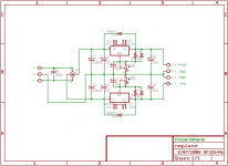
I just made this regulator for a power supply that I am building to test things such as small headphones amps and other devices I may create. It is my first time building a dual rail power supply and I would like some insight as to the types of components and values I have selected. I am going to be using a center-tapped 2x12v transformer (24v total) so hopefully I can get some usefull voltages out of this.
The regulator IC's are the well known lm317 and lm337. For C8 and C4 I will be using tantalum capacitors. With that aside, I'm not quite sure if I have the diodes in correctly, and also, what are some good values for C6 and C9?
Thank you very much!
-Chris
Attachments
moamps said:D4 is reversed.
Are you sure? I thought you would want it reverse biased. It is my understanding that the only time that diode will conduct is when the leads are shorted, so it draws the current around the IC instead of through it. Please carifiy if I am wrong
I think D4 protects regulator if power supply is shut down with a lot of capacitance on the ouput. If this happens, capacitors in the load can dump current back into the regulator. D4 shunts this current around the regulator.
You might also consider snubbers on the rectifier diodes for less switching noise. This is usually only a small improvement though.
- Rick
You might also consider snubbers on the rectifier diodes for less switching noise. This is usually only a small improvement though.
- Rick
I think you have a good circuit.
From a 2x12 Volt transformer, you will have like +- 17-18 Volt input.
This will give you at least +15 and -15 Volt output,
a bit depending on how much current load will take.
Max output current is 1.5A for a TO-220 LM317.
Say you have circuit taking +-1.0 A at +-5.0V.
Voltage across LM317 will be input-output = 18-5 = 13 Volt
13 Volt x 1.0A = 13 Watt in each IC.
You will need two medium sized heatsinks.
One for each IC. (if you use one common heatsink, you need isolation mounting pads)
(Worst case, +-1.5 A and +-1.25 Volt output
would give like 25 Watt in each IC.)
D1 and D3 are superfluous with the bypass capacitance of 10u you are using. As said D4 is the wrong way round. I would change the 240 ohm resistors to 120 ohm to meet the minimum chain current spec of the LM337.
C6 and C9 you already have good values, the more capacitance you use the more more stable the circuit but the longer power stays applied after turn off (to an extent) and the risk of damage to the regulator is increased (hence why D2 and D4 are employed).
Fair play if you want to design your own board, but take a look at my website where I have almost the same circuit with a nice PCB already done")
C6 and C9 you already have good values, the more capacitance you use the more more stable the circuit but the longer power stays applied after turn off (to an extent) and the risk of damage to the regulator is increased (hence why D2 and D4 are employed).
Fair play if you want to design your own board, but take a look at my website where I have almost the same circuit with a nice PCB already done
Alright guys, thanks for all the tips. I'll make sure that I put adaquate size heatsinks on these babies so they don't cook themselves for dinner. Either than that, I am happy with the circuit and since you guys gave the approval I am going to go ahead and get a board printed.
richie00boy: It would be nice to use your board, but this is a learning curve for me and I figured I would test the waters to see if I can actually make something for myself
richie00boy: It would be nice to use your board, but this is a learning curve for me and I figured I would test the waters to see if I can actually make something for myself
Not to confuse the issue with D4, but this is how I would look at it (and the proper direction of it), just as proposed by RDL2004:
Consider the LM337 negative regulator, and its input and output. Let us say that after powering your circuit down, the INPUT of the LM337 drops to ground almost instantly, while the OUTPUT of the LM337 remains at -15V (or whatever your desired negative voltage is) because of capacitive loading.
==> This means that the LM337 output is MORE negative than the LM337 input, and thus current could still be sucked out of the regulator, or a large voltage could develop across the regular (and damage it).
If you connect a diode with the anoded at the input and the cathode at the output of the LM337, the dioded conducts and prevents the voltage across the regulator from ever getting higher than ~.7V.
Sorry if this post is redundant, just my way of reasoning through it. Don't delete the diode alltogether; it can be a good protection measure.
- Status
- This old topic is closed. If you want to reopen this topic, contact a moderator using the "Report Post" button.
- Home
- Amplifiers
- Power Supplies
- Please critique my voltage regulator