Hi
I have a question.
I have a vintage linear power supply: transformer rated 200VA, +-43V without load 15A rectifier, ~7mF per side and want po power an audio amp with it.
My question is: can I measure the worst case voltage drop (max power, 4ohm load) simply putting a 8ohm load across rails? Is it safe?
Or could someone kindly share experience and tell me what worst case situation I can expect?
regards
Hi,
+-43V is the same as 86V into a single 8ohm load.
The power drawn will be P=V*V/R = 86*86/8=massive fireball.
If you load each winding simultaneously with an 8ohm load then the power from each winding will be 231W and total P=462W still damned hot.
A 37r across the 86V will give about 200W (if the voltage did not fall).
The +-43V will now fall to a new value and that measured V will allow you to calculate the % voltage drop and you can calculate the actual loaded current output (assuming the resistor can hold value as it heats up). You can estimate the regulation if you proportion the voltage drop * current back up to the design VA.
This explanation seems quite complex, give us the test numbers & we can guide you through the arithmetic to find the actual load that will just load the transfomer to it's maximum VA and then allow a retest giving an accurate measurement of it's regulation.
However two questions;- 1. do you need to know the regulation accurately before you build the equipment? 2. All these tests must be done at the rated primary voltage. How do you intend holding that accurately?
I guess the regulation will be between 7% and 9%. Any bets?
Just noticed you did not specify if the +-43Vac was actually +-43Vdc after the rectifier and smoothing. My calculations above are based on transformer straight into load without rectification and/or smoothing.
You can use two current sources.
Each current source is a TO3 high power transistor, at a LARGE HEATSINK.
You can use 2 NPN TO3 transistors for this.
One CCS (constant current source) is put between +V and 0V
and the other between 0V and -V.
Example:
you have 2x30 Volt DC.
Using two CCS set at 1.0 A current
will be a load: 2x30 x 1.0 = 60 Watt
Note:
These will be DC-current load.
Sinus ( RMS ) power will be twice of this test DC-load.
Say your amplifier will be a 100 Watt RMS max Output.
This is equal to a DC power load of 50 Watt.
Thanks for your precious answers.
Honestly I intend to run both high-power unregulated supply and regulated small signal supply.
The point is I want to adjust voltage of regulated one so that the amp will have good (hi-power) rail efficiency with flawless clipping behaviour.
Can I use diode 'clamp' in VAS stage, so that diodes switch on when either close to small signal rail voltage or above power rail voltage?
kind regards
P.S.By the way it was terribly loud when rail voltage dropped by 2V
Attachments
I think in general it should work if you take care about two points:
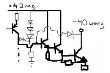
-The bias current through your 3 series diodes should be higher than your VAS can pull up.
(BTW I would prefer a 3.3V Zener or 5 diodes. 3 diodes are still quite close to the rail.)
-And how do you get 43V regulated from a 43V unregulated supply??
-The bias current through your 3 series diodes should be higher than your VAS can pull up.
(BTW I would prefer a 3.3V Zener or 5 diodes. 3 diodes are still quite close to the rail.)
-And how do you get 43V regulated from a 43V unregulated supply??
Hi ChocoHolic
Thank you for reply
Yes, I understand
Do you think it is far enough from saturation? Transistor is 2n5401.
No, it is not like that, no smps nor doublers, I've got two spare cheap 10W trafos from some time ago.
best regards
Thank you for reply
-The bias current through your 3 series diodes should be higher than your VAS can pull up.
Yes, I understand
I just quickly drawn it to show idea, actually the VAS stage is common base configuration and clips at collector voltage equal with base voltage, another words one diode drop Vce (~0.65V).I would prefer a 3.3V Zener or 5 diodes. 3 diodes are still quite close to the rail.
Do you think it is far enough from saturation? Transistor is 2n5401.
-And how do you get 43V regulated from a 43V unregulated supply??
No, it is not like that, no smps nor doublers, I've got two spare cheap 10W trafos from some time ago.
best regards
Hm, your supply sounds reasonable.
Regarding clipping of the VAS, I would recommend at least
1V Vce + max. voltage drop across the emitter resistor.
If you adjust the regulated voltage with some more margin above the unregulated, then you can skip the entire anit VAS clipping circuit, because the anti clipping diode of your darlington output stage will limit earlier than VAS would naturally clip.
- Status
- This old topic is closed. If you want to reopen this topic, contact a moderator using the "Report Post" button.
- Home
- Amplifiers
- Power Supplies
- Rail drop test