The current sensing approach won't work, neither the voltage regulation because the TL072 is driving the COMP pin directly, overriding the internal amplifier of the SG3525A which has high very low output current capabilities. Note that sensing the current in such a way introduces a considerable amount of output-voltage dependent offset. Also note that the TL072 stops working properly when any of the inputs or the output approaches to 2V or 3V above the negative supply rail.
Also, tying OUTA and OUTB to GND in a SG3525 won't probably yield the desired NORing effect between the outputs. I've never tried it nor seen it in any circuit, so you should try first everything in a breadboard and point-to-point fashion. You won't be able to debug the circuit once it's mounted in a double sided SMD PCB.
Also, tying OUTA and OUTB to GND in a SG3525 won't probably yield the desired NORing effect between the outputs. I've never tried it nor seen it in any circuit, so you should try first everything in a breadboard and point-to-point fashion. You won't be able to debug the circuit once it's mounted in a double sided SMD PCB.
That part, tying OUTA and OUTB to GND, and VC (the collectors of OUTA & OUTB) connected through a resistor to VCC+, I seen in the SG3525 datasheet.
Huh, I see, that using a high-side current sensing is quite a lot "pain in the *ss".
How can I measure the output current on the positive rail, without so much limitations?
Or, should I simply put the shunt-resistor to the negative rail? That would make my life easier") But I learn how to measure current on the + rail....
But I learn how to measure current on the + rail....
How should I connect the TL072 to the SG3525, to let the SG3525's internal opamp work properly? Just simply decrease the TL072's max. output current, by adding a series resistor to the TL072's output?
In a PWM motorcontroller circuit I saw a short-circuit protection, which used a transistor. The transistor's base was tyed to the shunt-resistor, emitter on the GND, and the collector pulled down the SOFTSTART pin to the ground. Do you think, this can work ?
Huh, I see, that using a high-side current sensing is quite a lot "pain in the *ss".
How can I measure the output current on the positive rail, without so much limitations?
Or, should I simply put the shunt-resistor to the negative rail? That would make my life easier
But I learn how to measure current on the + rail....How should I connect the TL072 to the SG3525, to let the SG3525's internal opamp work properly? Just simply decrease the TL072's max. output current, by adding a series resistor to the TL072's output?
In a PWM motorcontroller circuit I saw a short-circuit protection, which used a transistor. The transistor's base was tyed to the shunt-resistor, emitter on the GND, and the collector pulled down the SOFTSTART pin to the ground. Do you think, this can work ?
Think a bit... First of all: What behaviour are you expecting from a current limit circuit? Do you want to limit output average current, or maybe input peak current and thus inductor current (preventing saturation)? Do you want a linear limiting effect by means of output voltage reduction, or you want to shutdown the circuit forcing a restart each time the limit is exceeded?
Think a bit? That will hurt!
I expect that current limiting, by output voltage reduction.
Then, I think the picture, attached in my prev. post, isn't good for me.
I think, I have to stay at opamp based current limiting, and the current sense resistor is in the negative rail. But how can I "implement" an addidional opamp to the SG3525?
You were right, the datasheet from ST mentions that single switch option by grounding OUTA and OUTB.
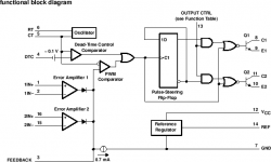
Concerning the current limiting, the key is to use a diode, so that the current amp can clamp the duty cycle during current limiting without disturbing it during normal operation. Note that an op-amp capable of swinging its output to ground is required for that purpose. You may want to check out TL494 datasheet since this IC includes two ORed error amplifiers.
Also, output current is not the rignt magnitude to limit because this doesn't protect the switches nor prevents inductor saturation, and I think that it will be prone to instability due to interaction between the output filter and the load. You should either limit input peak current or inductor average current instead. Shuting down the IC when a certain peak current is reached is quite easy, however, continuous current limiting requires either peak current sensing with slope compensation, or average current sensing.
Eva, you wrote:
So, do I need a "rail-to-rail" opamp?
I will think about this current-limiting thing... I would like to limit the max. output current, but now you mentioned, that this does not protect the switches from overcurrent.
an op-amp capable of swinging its output to ground is required for that purpose.
So, do I need a "rail-to-rail" opamp?
I will think about this current-limiting thing... I would like to limit the max. output current, but now you mentioned, that this does not protect the switches from overcurrent.
Hello!
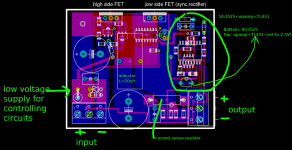
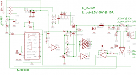
I attached the modified schematic.
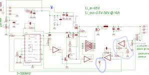
I circled the D2 diode. What type of diode should it be? 1N4148 is OK here? Or it must be a low forward voltaged diode? Maybe germanium-diode?
I put a blue X on the schematic. If I put there a current sense resistor, is that OK?
But ... I have seen many dc/dc buck regulator schematics. Thoose circuits were current limited, voltage stabilized. And i have never seen on them, that there's a current measuring on the input-rails of the circuit.
The opamps are right on the schematic?
Eva, thank you, your opinions, ideas, help!
I attached the modified schematic.
I circled the D2 diode. What type of diode should it be? 1N4148 is OK here? Or it must be a low forward voltaged diode? Maybe germanium-diode?
I put a blue X on the schematic. If I put there a current sense resistor, is that OK?
But ... I have seen many dc/dc buck regulator schematics. Thoose circuits were current limited, voltage stabilized. And i have never seen on them, that there's a current measuring on the input-rails of the circuit.
The opamps are right on the schematic?
Eva, thank you, your opinions, ideas, help!
Attachments
Hello!
Why is the that D2 diode backwards? In the TL494 datasheet, there the diode is connected the same way, as I draw. (see the attached image)
I think I will "implement" the inductor-current-sensing in the next version of this "experiment".
But I still don't understand, why I haven't seen any buck-regulator circuits with input-current-sensing. Is it too expensive? Or it degrades the efficiency too much?
Attachments
- Status
- This old topic is closed. If you want to reopen this topic, contact a moderator using the "Report Post" button.
- Home
- Amplifiers
- Power Supplies
- DC-DC buck regulator layout -> what's your opinion?